Video Monitoring System For School Buses

a video monitoring and school bus technology, applied in the field of video monitoring systems, can solve the problems of obstructing the driver's view, affecting the safety of drivers, and being relatively large in siz

Active Publication Date: 2008-07-03
ROSCO
View PDF9 Cites 25 Cited by
  • Summary
  • Abstract
  • Description
  • Claims
  • Application Information

AI Technical Summary

Benefits of technology

[0005]The present invention provides a unique and improved system which eliminates some blind spots for bus drivers and allows them to view their surroundings immediately adjacent all sides of the bus in a better manner. One or more video cameras are positioned on each side of the bus as replacements for the rearview mirrors typically utilized today. Preferably, two cameras are provided on each side of the bu...

Problems solved by technology

All of those mirrors are relatively large in size and create ...

Method used


Image

  • Video Monitoring System For School Buses
  • Video Monitoring System For School Buses
  • Video Monitoring System For School Buses

Examples


Embodiment Construction

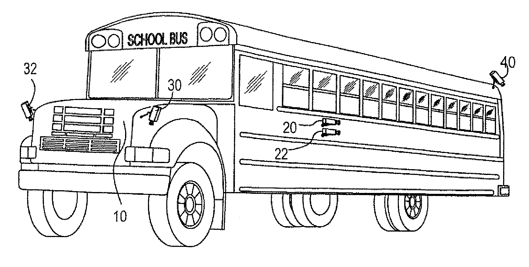
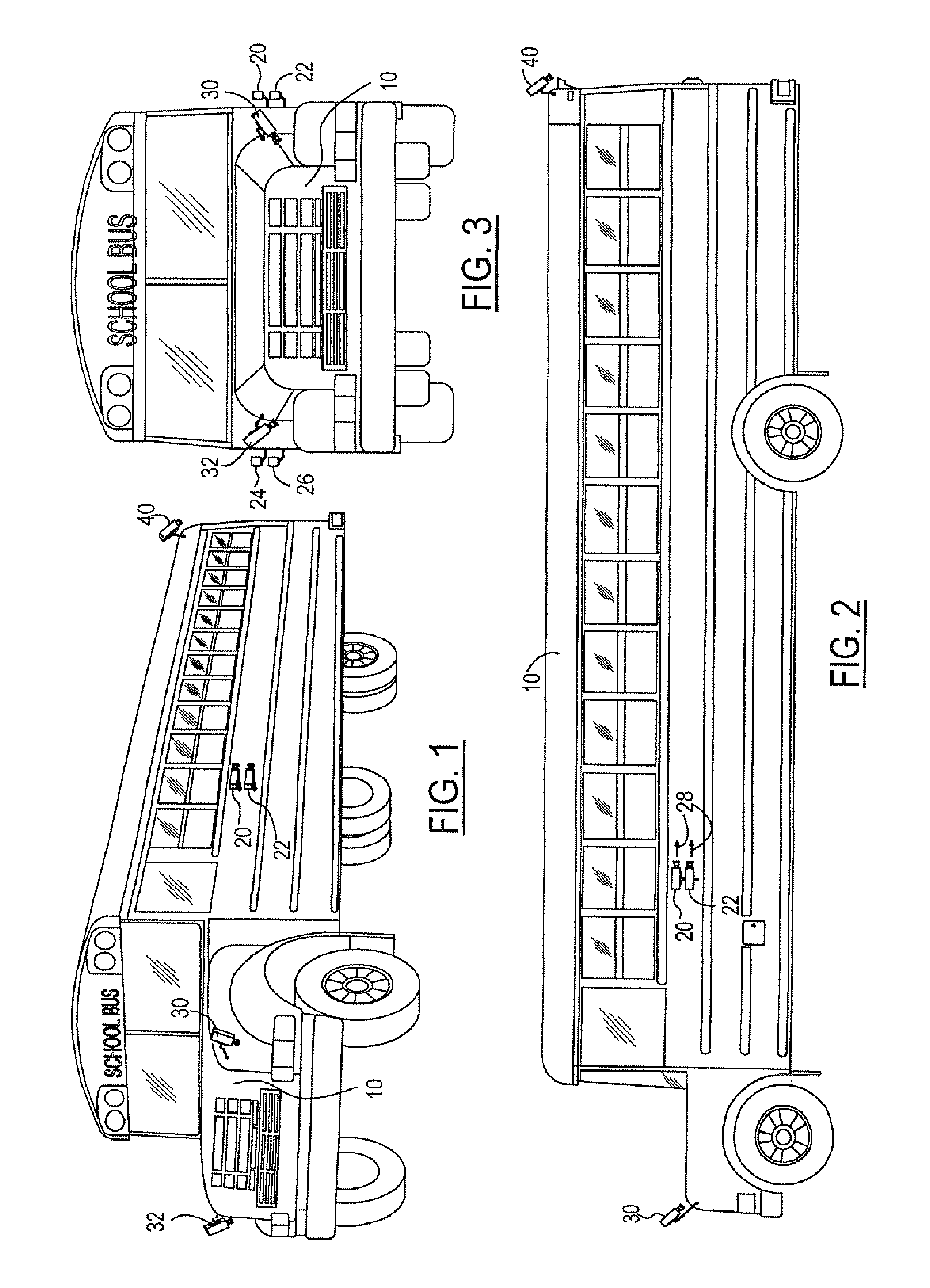
[0016]School buses today have their variety of mirrors that the drivers utilize to view the situations inside and outside of the vehicles, whether the school bus is moving or stationary. These mirrors allow the driver to view the surrounding situation and environment. Many of these mirrors, however, particularly the mirrors positioned on the sides of the school buses and on the front fenders, can create blind spots in the visibility of the drivers.

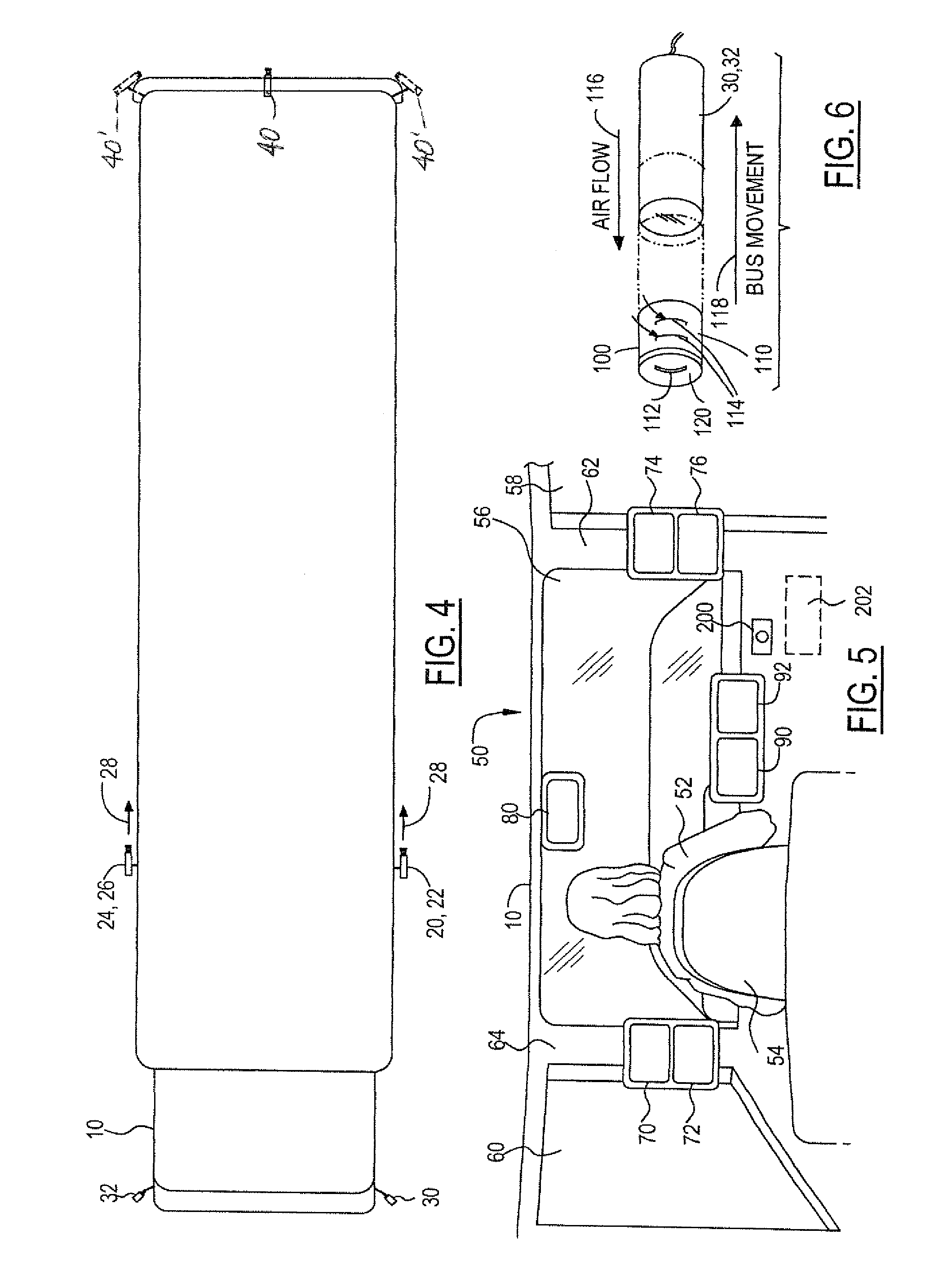
[0017]With the present invention, the mirrors typically utilized on the outside of the school bus are replaced by video cameras and the displays are shown in a plurality of monitors positioned at strategic locations inside the school bus. The cameras are mounted in non-obtrusive locations in order to allow increased visibility of the driver to the outside environment. The monitors inside the school bus can be positioned in locations that the driver is accustomed to looking at the outside mirrors so the drivers can easily switch from a scho...


PUM


Abstract

A video camera system for a school bus to replace one or more of the mirror systems typically utilized on school buses today. One or two cameras can be positioned on the sides of the school bus in place of the rearview mirrors presently utilized. A pair of cameras with wide-angle lenses can be positioned on the front fenders of the school bus to replace the cross view mirrors currently used today. One or more cameras can also be positioned on the rear of the school bus to display the environment immediately behind the school bus. Video monitors displaying the images from the cameras can be positioned in the cab of the school bus for viewing by the driver. The monitors from the cameras positioned on the sides of the school bus can be positioned on the A-pillars of the school bus approximately in the locations presently occupied by the rearview mirrors outside of the school bus. The monitors for the cross-view mirrors can be positioned on the dashboard or instrument panel of the school bus, preferably to the right side of the driver and adjacent the egress door. The monitor for the camera(s) on the rear of the bus can be positioned on the windshield of the vehicle. A portable computer could also be provided in place of the stationary monitors, and a central recording system can be utilized to retain the images from all of the cameras for subsequent monitoring purposes.

Description

TECHNICAL FIELD [0001]The present invention relates generally to video monitoring systems and more particularly to video monitoring systems for school buses.BACKGROUND OF THE INVENTION [0002]School buses are presently equipped with a variety of mirrors for use in assisting the driver to view surroundings and the situation around all areas of the bus. Presently, one or more rear view mirrors are positioned on each side of the school buses so that the driver can view the situation along the sides of the school bus and in the distance behind the school bus. In addition, school buses are provided in their front forward corners with cross-view mirrors. Cross-view mirrors are generally convex in shape and provide the driver with a field of view in the front of the bus and along the sides of the bus so that the driver can see children crossing in front of the bus and walking along the sides of the bus.[0003]When the bus is moving, the driver uses the two side view mirrors in the same manne...

Claims


Application Information

Patent Timeline
IPC IPC(8): H04N7/18
CPCB60R1/00H04N7/181B60R2300/102
Inventor SCHMIDT, WILLIAM P.SWAIN, DANIEL M.
Owner ROSCO
Why Eureka
Try Eureka