Dynamic dashboard display

a dashboard display and dynamic technology, applied in the field of vehicle information displays, can solve the problems of not having adjustable gauges or information panels, affecting the ability of people to adjust their eyes, and a certain amount of time, so as to facilitate advanced functions

Inactive Publication Date: 2011-07-21
KARPINSKY DMITRY
View PDF7 Cites 130 Cited by
  • Summary
  • Abstract
  • Description
  • Claims
  • Application Information

AI Technical Summary

Benefits of technology

[0012]The object of the present invention provides information to an operator and occupants of the motor vehicle through an electronic dynamic dashboard display. The display system is designed to serve as a centralized control point for most vehicle comfort, entertainment, safety and information display functions. The use of microprocessor based display controller of this type also facilitates advanced functions such as sophisticated trip computer functions, online Internet connectivity, Bluetooth connectivity and synchronization with personal digital assistants, mobile phone, voice response, GPS functionality and mapping including traffic, weather, location-based networking and integration with home automation and external computers, to name a few. Parts of the display are touch sensitive which allow user to adjust settings such as radio, climate control system, GPS unit or move gauges around. The display can also, inform the occupants about any road hazards, warnings or present information in a human voice. The display gauges may be adjusted moved, resized, added or deleted by the vehicle occupant. For example, during a long trip, a speedometer may be in the middle of the dash, while when the same truck is pulling a heavy load, tachometer may be displayed where speedometer once was. Another example is of a driver driving along the freeway when a deer jumps in front of the vehicle. At that instance the vehicle avoidance system detects the deer and the main speedometer gauge disappears and is replaced with a warning blinking sign with sound indicating to the driver that there is imminent danger. These displays may be changed by vehicle occupants or set by manufacturer. Instead of being hard-wired or fastened into the dash, the displays will be dynamic within the electronic dashboard.

Problems solved by technology

A few patents (D494908, D493757, D492632, D469391) discussed configuration of the dashboard, but those do not have electronic information displays contouring the vehicle, nor do they have adjustable gauges or information panels.
If the instrumentation is small or cannot be read quickly, or if driver reads several gauges in same glance, an even greater time will elapse.
In addition, a person's eyes take a certain amount of time to adjust when shifting focus from a distant point to a proximate point, and a similar time elapses when attention is returned to the distant point.
Changes in lighting between the interior and exterior of the vehicle can also make it difficult to switch focus between the road and the dashboard.
The constant shifting of attention from the road to the instruments and the re focusing of eyes involved in this process can be distracting and had the potential to contribute to the occurrence of accidents.
However, this technology still presents the same gauges, in fixed position, and is often difficult to read in daylight hours.
No one has previously provided Dynamic Dashboard Displays for vehicles.

Method used


Image

  • Dynamic dashboard display
  • Dynamic dashboard display
  • Dynamic dashboard display

Examples


Embodiment Construction

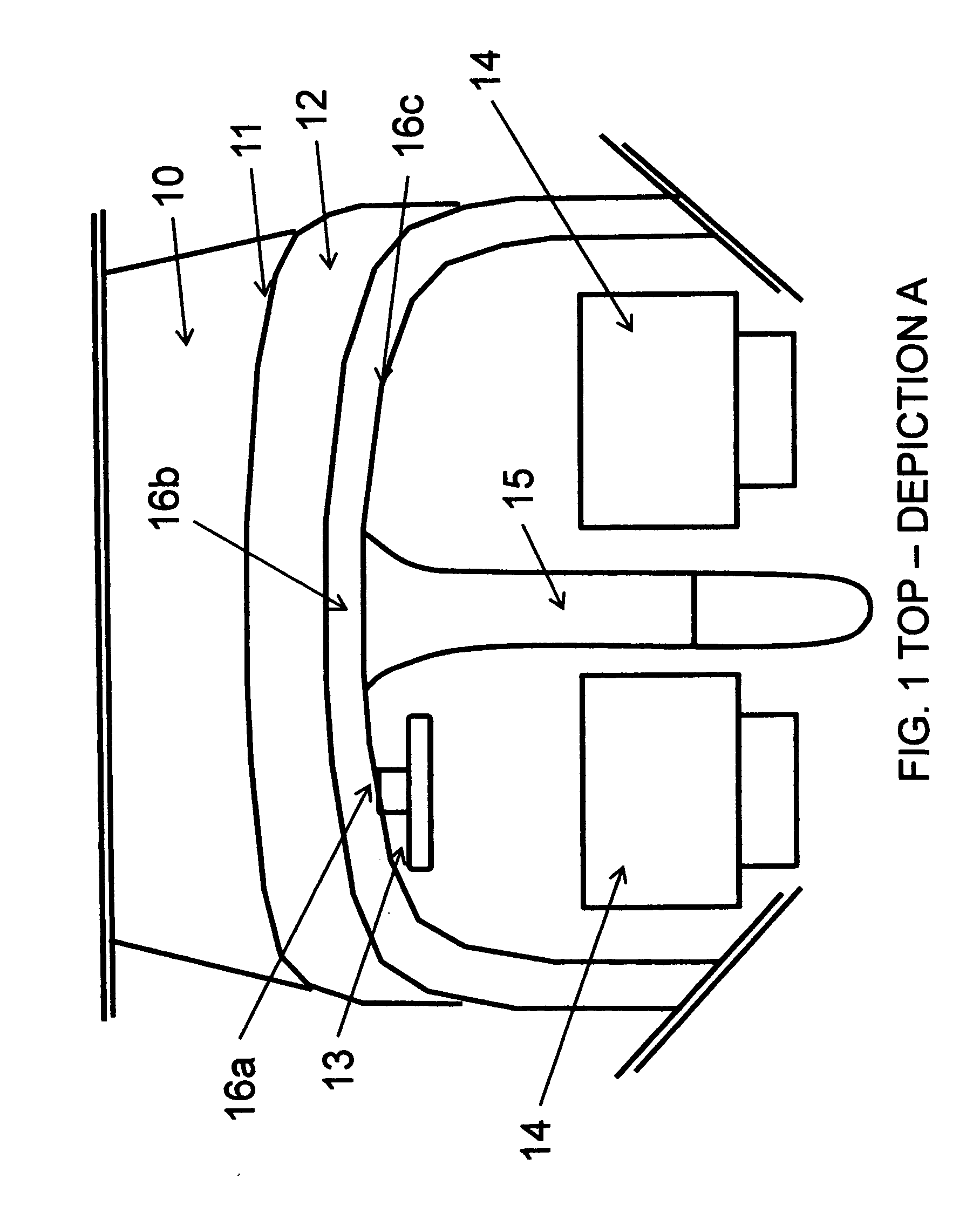
[0028]For the purposes of the following description, the terms “upper,”“lower,”“right,”“left,”“vertical,”“horizontal,” and derivatives or equivalents thereof shall relate to the invention as oriented in FIG. 1. It is understood that the invention may assume various alternative orientations, except where expressly specified to the contrary. It is also understood that the specific devices and processes illustrated in the attached drawings, and described in the following specification, are simply exemplary embodiments of the inventive concepts defined in the appended claims. Hence, specific dimensions and other physical characteristics relating to the embodiments disclosed herein are not considered limiting unless the claims expressly state otherwise. Accordingly, various modifications may be made without departing from the spirit of scope of the general inventive concept as defined by the appended claims and their equivalents.

[0029]An embodiment of the present invention will be descri...


PUM


Abstract

This invention relates to an electronic instrument panel for vehicles consisting of information display that provides on-demand imaging where instruments are not in static, fixed position, but rather change in location, dimension, information presented based on conditions and environment the vehicle is in, and based on user or factory preferences and settings. The display can change colors, be self dimming and offer wide array of telemetry, entertainment, vehicle data, climate control, instrumentation, and powertrain information. The instrument panel will be online through wireless connectivity and provide the occupants real-time on-demand information about the vehicle and its surroundings through electronic display and human voice.

Description

[0001]This application is a continuation-in-part of Ser. No. 12 / 499,128 files on Jul. 8, 2009, which is hereby incorporated by preference, as is set forth in full in this document, for all purposes.CROSS REFERENCE TO RELATED APPLICATIONS[0002]Patent #TitleDate IssuedD571271Meter panel for an automobileJun. 17, 2008D562748Instrument panel for an automobileFeb. 26, 2008D557646Vehicle dashboard panelDec. 18, 2007D546744Meter for motorcyclesJul. 17, 2007D543139Instrument cluster for a vehicleMay 22, 2007D531557Instrument clusterNov. 7, 2006D529847Instrument gauge clusterOct. 10, 2006D529423Vehicle instrument clusterOct. 3, 2006D512357Instrument panelDec. 6, 2005D512006Instrument panelNov. 29, 2005D499998Instrumental panel for automobilesDec. 21, 2004D494908Surface configuration of a dashboard for a vehicleAug. 24, 2004D493757Surface configuration of a dashboard for a vehicleAug. 3, 2004D493756Instrument panel for an automobileAug. 3, 2004D492632Surface configuration of a dashboard for a...

Claims


Application Information

Patent Timeline
Patent Type & Authority Applications(United States)
IPC IPC(8): B60Q1/00G08B23/00
CPCB60K35/00B60K37/06B60K2350/1004B60K2350/1032B60K2350/1044B60Y2200/12B60K2350/1072B60K2350/1096B60K2350/357B60K2350/403G01D7/00B60K2350/1064B60K2370/11B60K2370/1442B60K2370/148B60K2370/1515B60K2370/154B60K2370/155B60K2370/186B60K2370/589G01D2207/10G01D2207/30
Inventor KARPINSKY, DMITRY
Owner KARPINSKY DMITRY
Why Eureka
Try Eureka