Video surveillance equipment and video surveillance system
a technology which is applied in the field of video surveillance equipment and video surveillance system, can solve the problem that the left object itself cannot be recognized
- Summary
- Abstract
- Description
- Claims
- Application Information
AI Technical Summary
Benefits of technology
Problems solved by technology
Method used
Image

Examples
first embodiment
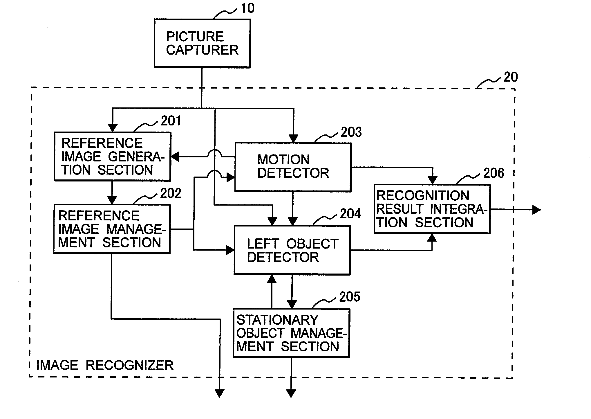
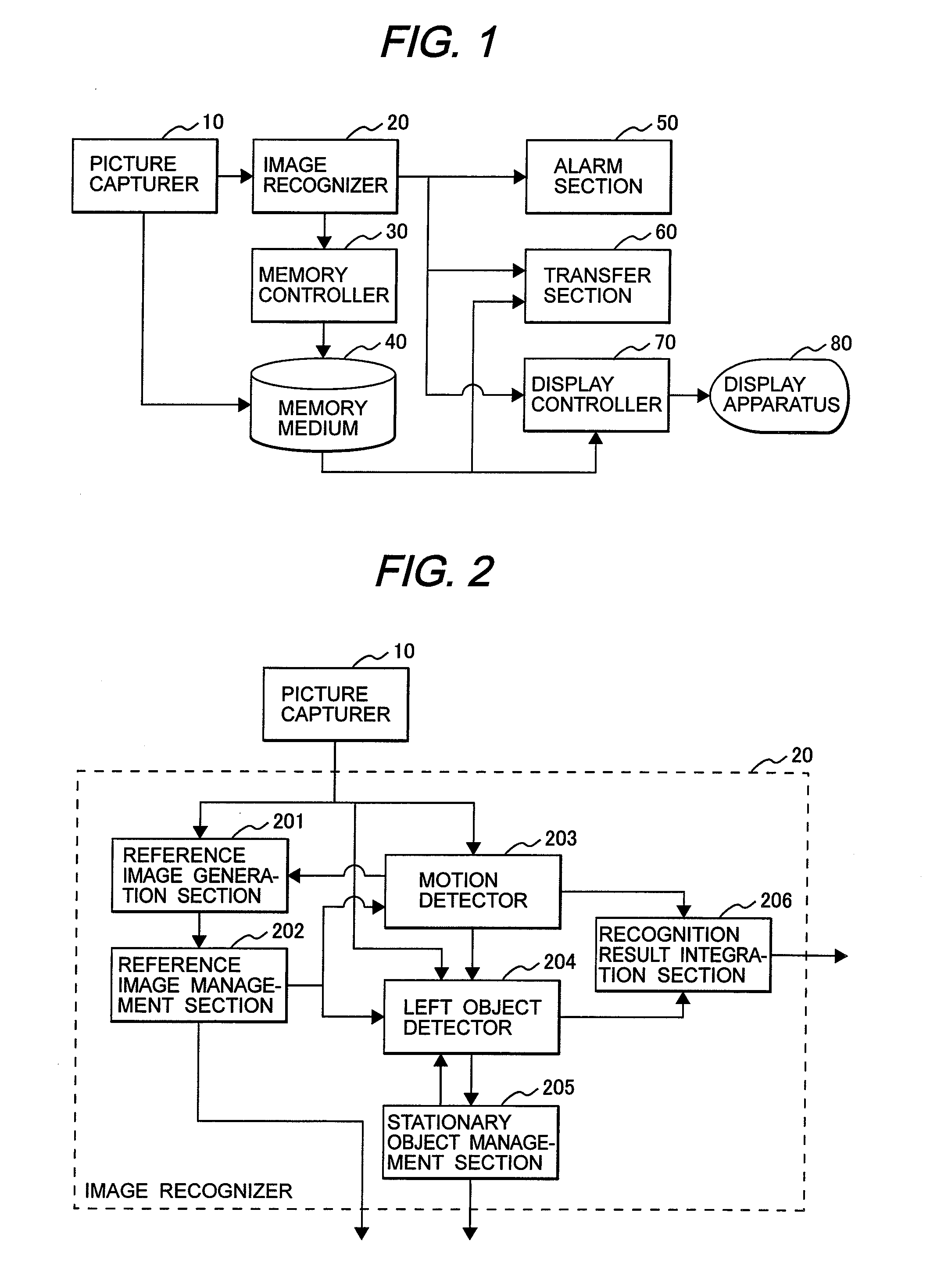
[0026]An embodiment of the present invention will be described with reference to the drawings. FIG. 1 shows the overall structure of a video surveillance system of the present embodiment. From the viewpoint of hardware, the structure comprises a computer system including a central processing unit (CPU), and its individual functions are executed. The video surveillance system is provided with a picture capturer 10 for capturing signals obtained from one or more imaging devices such as TV cameras as pictures, an image recognizer 20 for recognizing moving objects and left objects by image recognition processing using the image data obtained from the picture capturer 10, a memory controller 30 for controlling the store of pictures and the compression ratio and store interval of recorded pictures based on results calculated by the image recognizer 20, a memory medium 40 for storing the pictures obtained from the picture capturer 10 based on commands from the memory controller 30, an alar...
second embodiment
[0046]A video surveillance system of second embodiment, in which an arrangement for acquiring information about a face, clothes, and the like is added to the video surveillance system of the first embodiment, will be described with reference to FIG. 8. The information obtained by the motion detector 203 and the information obtained by the left object detector 204 is input in the recognition result integration section 206. A personal information detector 800 can extract, from these input information, data about a person near a left object at the time when the object was left so as to implement a function to store, transfer, or display the extracted personal data. Specifically, an area determined as including a person based on the results of face detection processing, head detection processing, size decision, and the like is extracted from an area determined by the motion detector 203 as including a motion, and the picture information about the extracted area is then stored in the mem...
third embodiment
[0048]In the left object detection method of the present invention described in the first embodiment, pictures input to the image recognizer 20 may be picture data already stored in the memory medium 40. That is, a function to search for the stored pictures can be implemented. FIG. 10 shows a video surveillance system, in which the function is implemented, of third embodiment. The video surveillance system of third embodiment arranges a search controller 1000 between the memory medium 40 and the image recognizer 20. An object to be searched for from a human interface is specified on the display section 80. In a case where this video surveillance system is used in state that detection of left objects is not set, the video surveillance system can use to check pictures on which such an object is set when a suspicious left object may be found later.
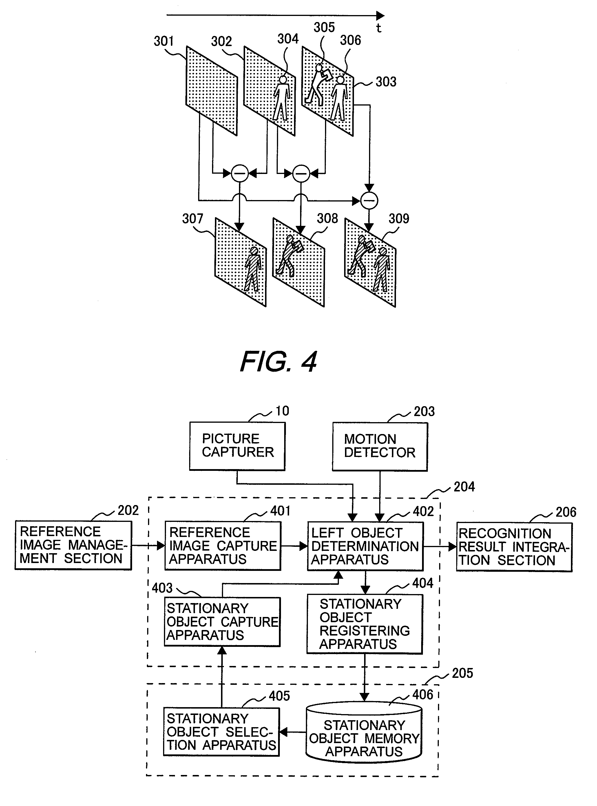
[0049]FIG. 11 illustrates how to specify an object. An area of an object can be set by specifying an upper left corner thereof as the start ...
PUM
 Abstract
- an area detection apparatus for detecting a second image area being stationary for a predetermined time in a first image area which is an area differing between a reference image used as a reference in image processing and the input images;
- a memory apparatus for storing image of the detected second image area; and
- an image comparison apparatus for performing comparison processing a plurality of times between the stored image and image in the second image area included in the input images.
Description
Claims
Application Information
 - R&D Engineer
- R&D Manager
- IP Professional
- Industry Leading Data Capabilities
- Powerful AI technology
- Patent DNA Extraction
Browse by: Latest US Patents, China's latest patents, Technical Efficacy Thesaurus, Application Domain, Technology Topic.
© 2024 PatSnap. All rights reserved.Legal|Privacy policy|Modern Slavery Act Transparency Statement|Sitemap