
Method and apparatus for remote device control using control signals superimposed over ethernet

a technology of remote control and control signals, applied in the direction of electric controllers, ignition automatic control, instruments, etc., can solve the problems of high difficulty in cabling, powering and interfacing different products, consuming a large amount of power for the backlight of the display device, and limited li

Active Publication Date: 2008-07-03
GARMIN
View PDF11 Cites 12 Cited by
  • Summary
  • Abstract
  • Description
  • Claims
  • Application Information

AI Technical Summary

Problems solved by technology

If power is not removed, the battery may be drained when the user returns to the marine craft.
Some marine craft utilize a large number of sensors and display devices, creating a high level of difficulty with cabling, powering, and interfacing the different products which provide different types of information.
In addition, the backlight of the display device consumes a large amount of power and has a limited life.
Unfortunately, if power is removed from the display device the data which has been collected or received by the sensors is lost.
Some forms of data, such as data received from a satellite, are time consuming to acquire and thus it is not advantageous to turn the display device off.

Method used


Image

  • Method and apparatus for remote device control using control signals superimposed over ethernet
  • Method and apparatus for remote device control using control signals superimposed over ethernet
  • Method and apparatus for remote device control using control signals superimposed over ethernet

Examples


Embodiment Construction

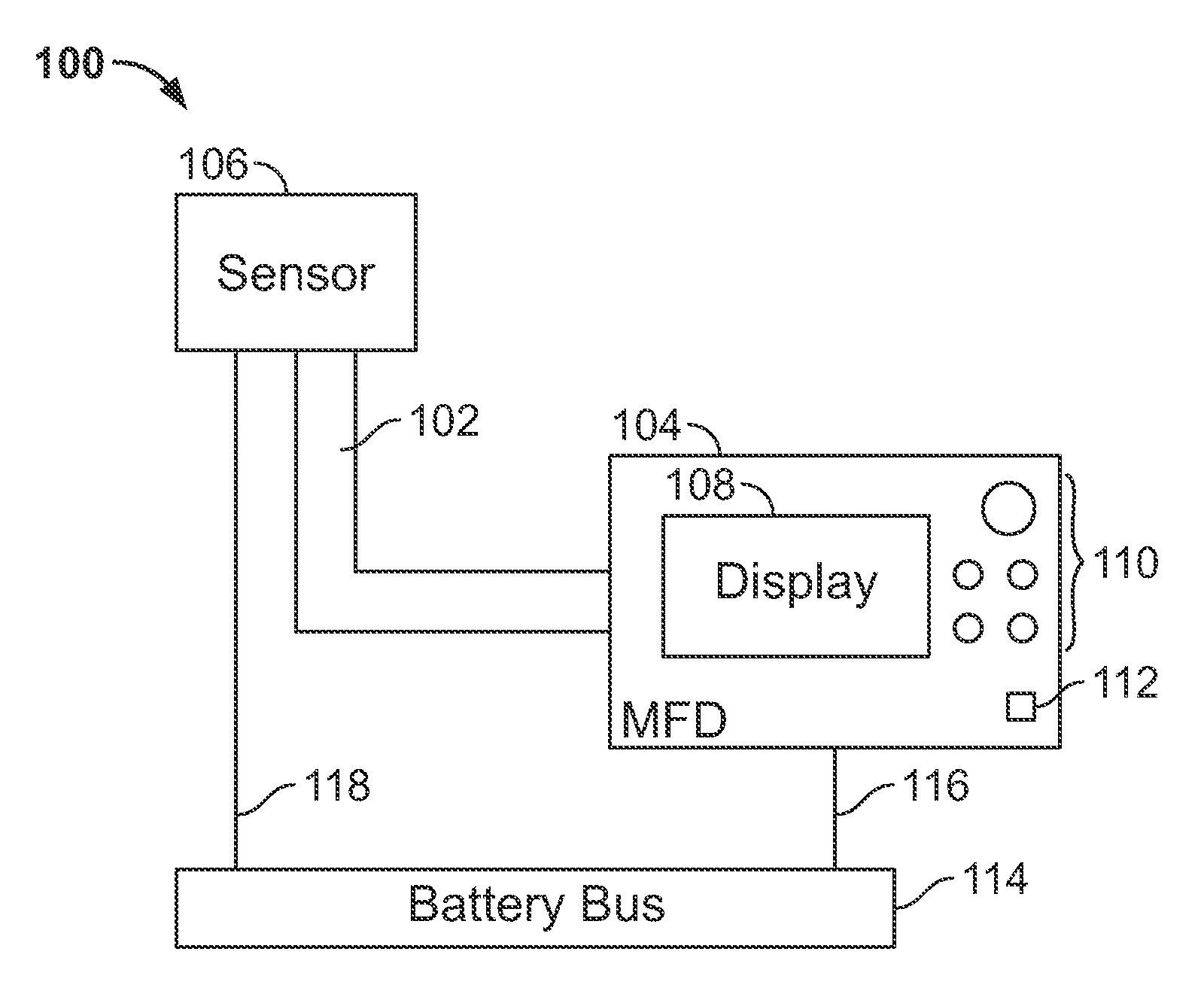
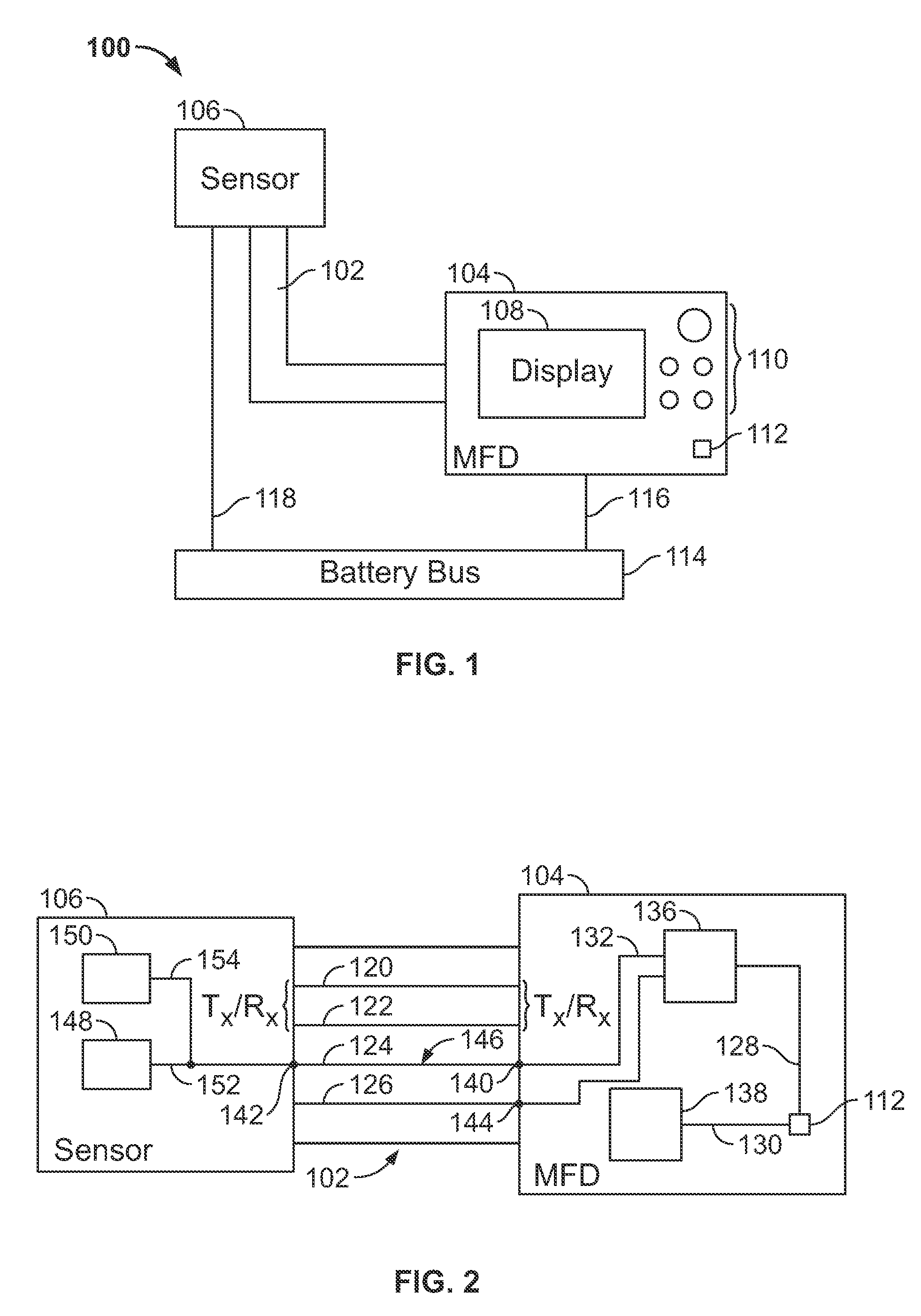
[0015]FIG. 1 illustrates a network 100 having devices interconnected with an Ethernet cable 102 in accordance with an embodiment of the present invention. The network 100 includes a multi-function display (MFD) 104 and a sensor 106 interconnected with the Ethernet cable 102. The MFD 104 and the sensor 106 are each connected to a ground and battery bus 114 by way of lines 116 and 118, respectively. It should be understood that one or more battery or power sources may be provided instead of the battery bus 114. Therefore, only two separate connections, a network connection and a power connection, need to be provided to each MFD 104 and sensor 106.

[0016]Some networks utilize IEEE 802.3af power over Ethernet, which superimposes power over the Ethernet cable to run devices connected to the Ethernet. Thus, if three devices are interconnected on a network with an Ethernet cable, one device can superimpose power over the Ethernet cable to supply the necessary power to the other two devices....


PUM


Abstract

A method and apparatus for remotely controlling a power state of devices comprises interconnecting, with an Ethernet cable, a first multi-function display (MFD) and at least one device for communicating with the first MFD. The first MFD comprises a switch for changing a power state. A power source provides power for the first MFD and the at least one device. The first MFD remotely controls the power state of the at least one device through a control signal output to the Ethernet cable. The at least one device receives the control signal and changes the power state of the at least one device in response to the control signal.

Description

RELATED APPLICATION[0001]The present application is a continuation of and claims priority benefit to U.S. patent application Ser. No. 11 / 140,792, filed May 31, 2005, entitled “METHOD AND APPARATUS FOR REMOTE DEVICE CONTROL USING CONTROL SIGNALS SUPERIMPOSED OVER ETHERNET.” The above-identified application is hereby incorporated by reference.BACKGROUND OF THE INVENTION[0002]This invention relates generally to remotely controlling devices which are interconnected, and more particularly, to controlling devices interconnected with Ethernet cable.[0003]Multiple sensors are often used aboard a marine craft to provide information to a user. Types of information may be weather, radar, or global positioning, for example. It is helpful to have the different types of information collected and, if possible, integrated together, then displayed on one or more devices. A small boat may utilize a single device for providing information, while larger craft may have multiple devices installed on more...

Claims


Application Information

Patent Timeline
Patent Type & Authority Applications(United States)
IPC IPC(8): H04B3/00
CPCG06F1/3209G06F1/266
Inventor MEHAN, CRAIG L.
Owner GARMIN
Learn More