Fuel injection control apparatus and method for internal combustion engine

Active Publication Date: 2008-07-03
HONDA MOTOR CO LTD
View PDF11 Cites 12 Cited by
  • Summary
  • Abstract
  • Description
  • Claims
  • Application Information

AI Technical Summary

Benefits of technology

[0014]Preferably, the fuel injection control apparatus for an internal combustion engine further comprises load detecting means for detecting a load of the internal combustion engine; total required fuel amount calculating means for calculating a total required fuel amount required for the whole cylinder based on the detected load of the internal combustion engine; and engine temperature detecting means for detecting a temperature of the internal combustion engine, wherein the in-cylinder injected fuel behavior parameter calculating means calculates the in-cylinder injected fuel behavior parameter in accordance with one of the calculated total required fuel amount and the required in-cylinder injection amount and the detected temperature of the internal combustion engine, and the port injected fuel behavior parameter calculating means calculates the port injected fuel behavior parameter in accordance with one of the total required fuel amount and the required port injection amount and the temperature of the internal combustion engine.
[0015]Generally, a degree to which the fuel sticks to the inner wall surfaces of the intake system and combustion chamber is largely affected by the temperature of the internal combustion engine, and is larger as the temperature is lower because the fuel is less apt to vaporize. Also, the required fuel injection amount represents a load on the internal combustion engine, and additionally reflects the thickness of a fuel film sticking to the inner wall surface of the intake system, and the like, unlike other load parameters. Therefore, according to the present invention, the in-cylinder injected fuel behavior parameter can be appropriately calculated in accordance with one of the total required fuel amount and the required in-cylinder injection amount and the temperature of the internal combustion engine. Also, the in-cylinder injected fuel behavior parameter can be appropriately calculated in accordance with one of the total required fuel amount and the required port injection amount and the temperature of the internal combustion engine. Consequently, it is possible to more appropriately determine the net in-cylinder injection amount and the net port injection amount in accordance with both fuel behavior parameters.
[0016]Preferably, the fuel injection control method for an internal combustion engine further comprises the step of detecting a load of the internal combustion engine; calculating a total required fuel amount required for the whole cylinder based on the detected load of the internal combustion engine; and detecting a temperature of the internal combustion engine, wherein the in-cylinder injected fuel behavior parameter calculating step includes calculating the in-cylinder injected fuel behavior parameter in accordance with one of the calculated tot

Problems solved by technology

However, in the conventional fuel injection control apparatus, a correction against the sticking is made only for a fuel injected from the port fuel injection valve, so that a fuel transport behavior of the whole cylinder, including the sticking of a fuel injected from the in-cylinder fuel injection valve, is not reflected.
As a result, the amount of fuel actually used in the combustion in the combustion chamber cannot be appropriately controlled, failing to achieve a desired air-fuel ratio.
Also, in this fuel injection control apparatus, the correction against the sticking is performed exclusively in an oper

Method used


Image

  • Fuel injection control apparatus and method for internal combustion engine
  • Fuel injection control apparatus and method for internal combustion engine
  • Fuel injection control apparatus and method for internal combustion engine

Examples


Embodiment Construction

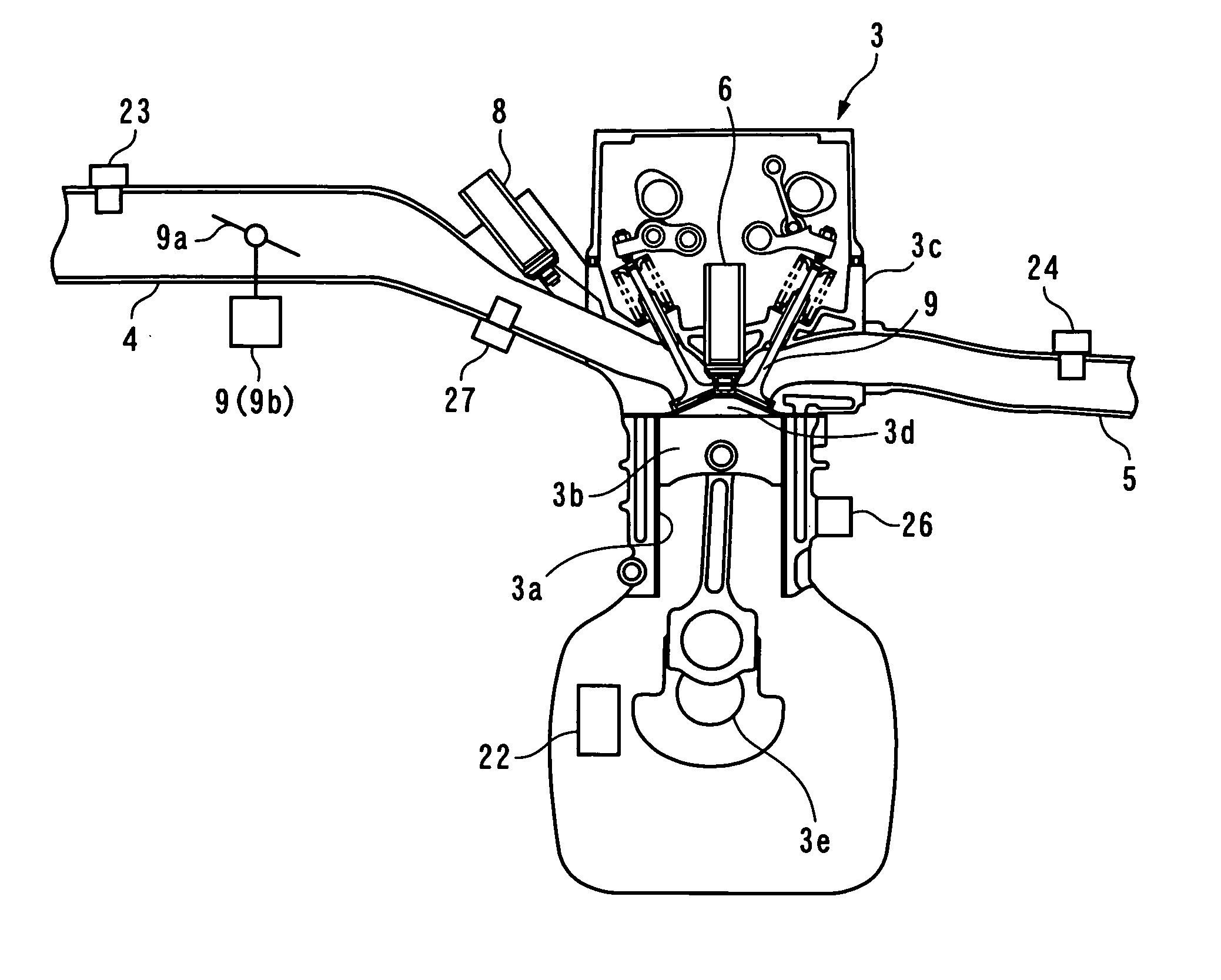
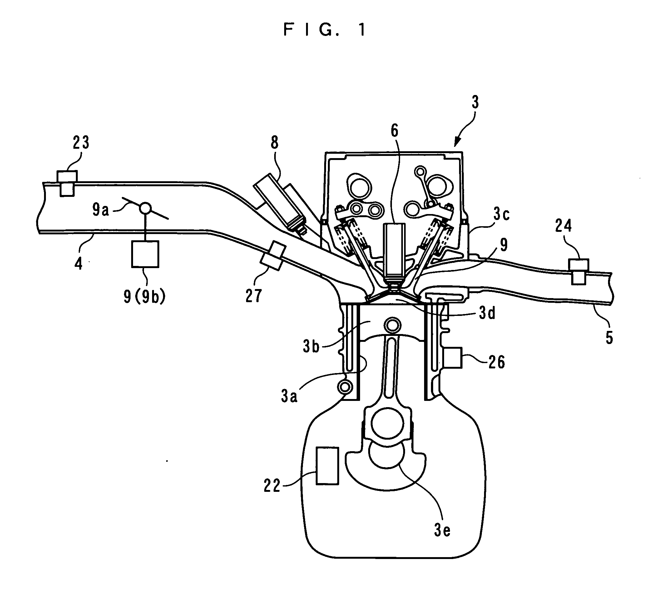
[0038]In the following, a preferred embodiment of the present invention will be described with reference to the drawings. FIG. 1 generally shows an internal combustion engine 3 to which a fuel injection control apparatus 1 according to this embodiment is applied. The internal combustion engine (hereinafter referred to as the “engine”) 3 is, for example, an in-line four-cylinder type four cycle gasoline engine which is equipped in a vehicle (not shown).

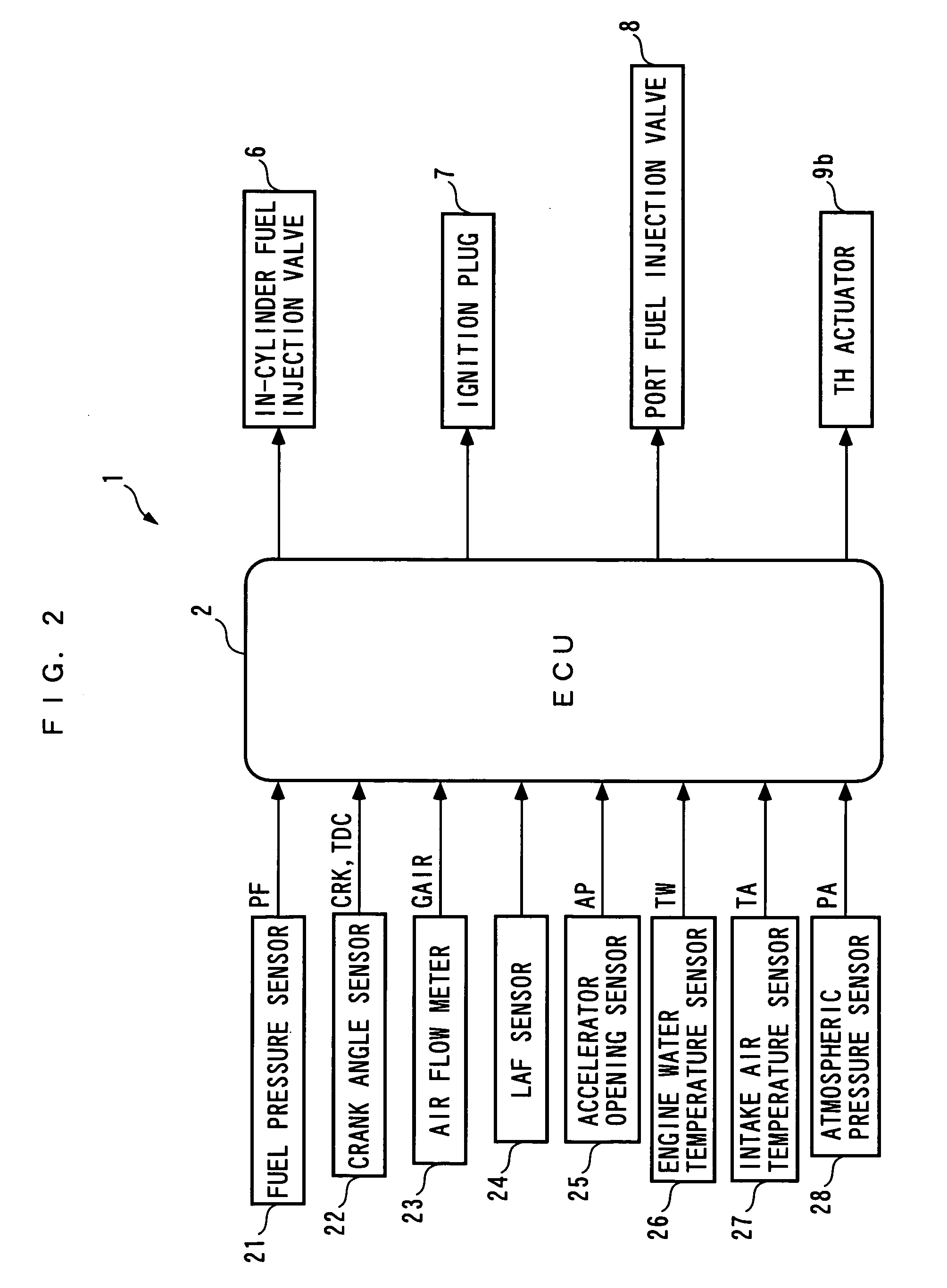
[0039]A cylinder head 3c of the engine 3 is connected to an intake pipe 4 (intake system) and an exhaust pipe 5 for each cylinder 3a, and an in-cylinder fuel injection valve 6 and an ignition plug 7 (see FIG. 2) are attached to face a combustion chamber 3d (only one each of which is shown in FIG. 1). This in-cylinder fuel injection valve 6 is configured to inject a fuel in the vicinity of an ignition plug 7 within the cylinder 3a. Also, a valve opening time and valve opening / closing timings of the in-cylinder fuel injection valve 6, as...


PUM


Abstract

A fuel injection control apparatus and method for an internal combustion engine are provided for appropriately controlling the amounts of fuel supplied from an in-cylinder fuel injection valve and a port fuel injection valve to a cylinder in a simple control approach while satisfactorily reflecting a fuel transport behavior as a whole cylinder. An ECU calculates a required in-cylinder injection amount and a required port injection amount, calculates an in-cylinder injected fuel behavior parameter of a fuel from the in-cylinder fuel injection valve and a port injected fuel behavior parameter of the fuel from the port fuel injection valve, a net in-cylinder injection amount in accordance with the in-cylinder and port injected fuel behavior parameters based on the required in-cylinder injection amount, and a net port injection amount in accordance with the in-cylinder and port injected fuel behavior parameters based on the required port injection amount.

Description

BACKGROUND OF THE INVENTION[0001]1. Field of the Invention[0002]The present invention relates to a fuel injection control apparatus and method for an internal combustion engine which is supplied with a fuel by an in-cylinder fuel injection valve for injecting the fuel into a cylinder, and a port fuel injection valve for injecting the fuel into an intake system including an intake port.[0003]2. Description of the Prior Art[0004]Conventionally, as this type of fuel injection control apparatus for an internal combustion engine, one described, for example, in Laid-open Japanese Patent Application No. 2005-337102 is known. In this fuel injection control apparatus, the proportion of an in-cylinder injection amount injected from an in-cylinder fuel injection valve to a port injection amount injected from a port fuel injection valve is set in accordance with a detected operating condition of an internal combustion engine. Also, when the proportion of the port injection amount decreases whil...

Claims


Application Information

Patent Timeline
IPC IPC(8): F02D41/36
CPCF02D41/047F02D41/3029F02D41/3041F02D2041/389F02D41/3094F02D2041/3052F02D41/3047F02D2200/021
Inventor SHINOHARA, TOSHINARIOGAWA, KENKITAMURA, TORUITOGA, CHIHO
Owner HONDA MOTOR CO LTD
Why Eureka
Try Eureka