
Apparatus and method for moving logs within cutting-off machines

Inactive Publication Date: 2008-07-10
PERINI
View PDF8 Cites 2 Cited by
  • Summary
  • Abstract
  • Description
  • Claims
  • Application Information

AI Technical Summary

Benefits of technology

[0013]The present invention makes it possible to continuously feed the logs to cutting means, with no interruptions nor empty spaces between consecutive logs, which allows improving significantly the actual output of the system and without any interference between the means for driving the logs and the cutting means. Moreover, an apparatus according to the invention is relatively easy to make, cost-effective and reliable even after a prolonged service life.

Problems solved by technology

In particular, the feeding of the logs to the cutting means is of discontinuous nature, as an empty space results all the time between one log and the next, and because it is in fact impossible to use the system with porters of known type to feed the logs continually.
Such discontinuity in the supply brings about a decreased production, in terms of number of rolls per hour being produced, with respect to the actual capacity of the system.
A further drawback is that the components of the system are likely to collide with each other in case of failures in the system predisposed for moving the porters and the cutting means in synchronism, which affects negatively the economy of the manufacturing process.

Method used


Image

  • Apparatus and method for moving logs within cutting-off machines
  • Apparatus and method for moving logs within cutting-off machines
  • Apparatus and method for moving logs within cutting-off machines

Examples


Embodiment Construction

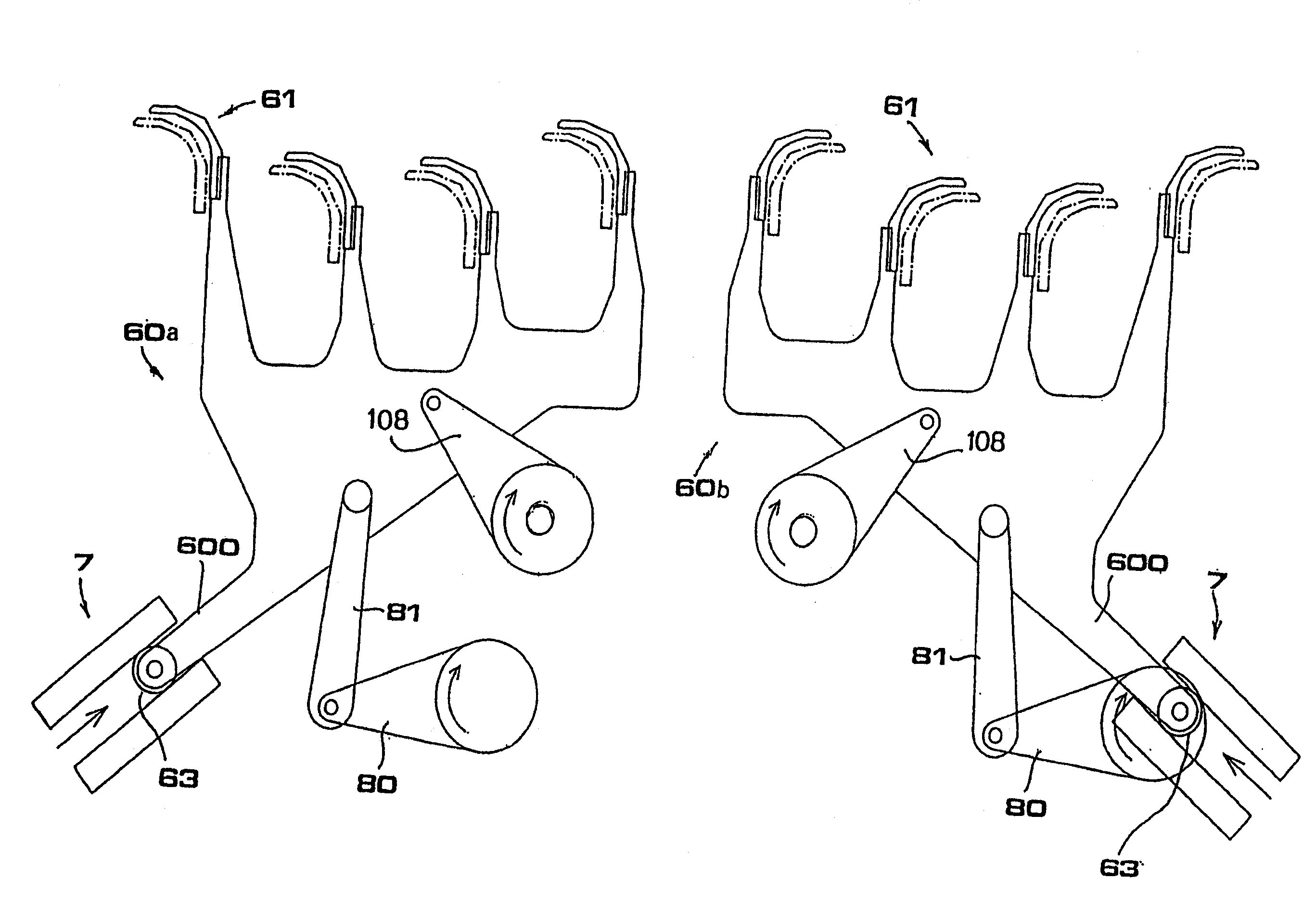
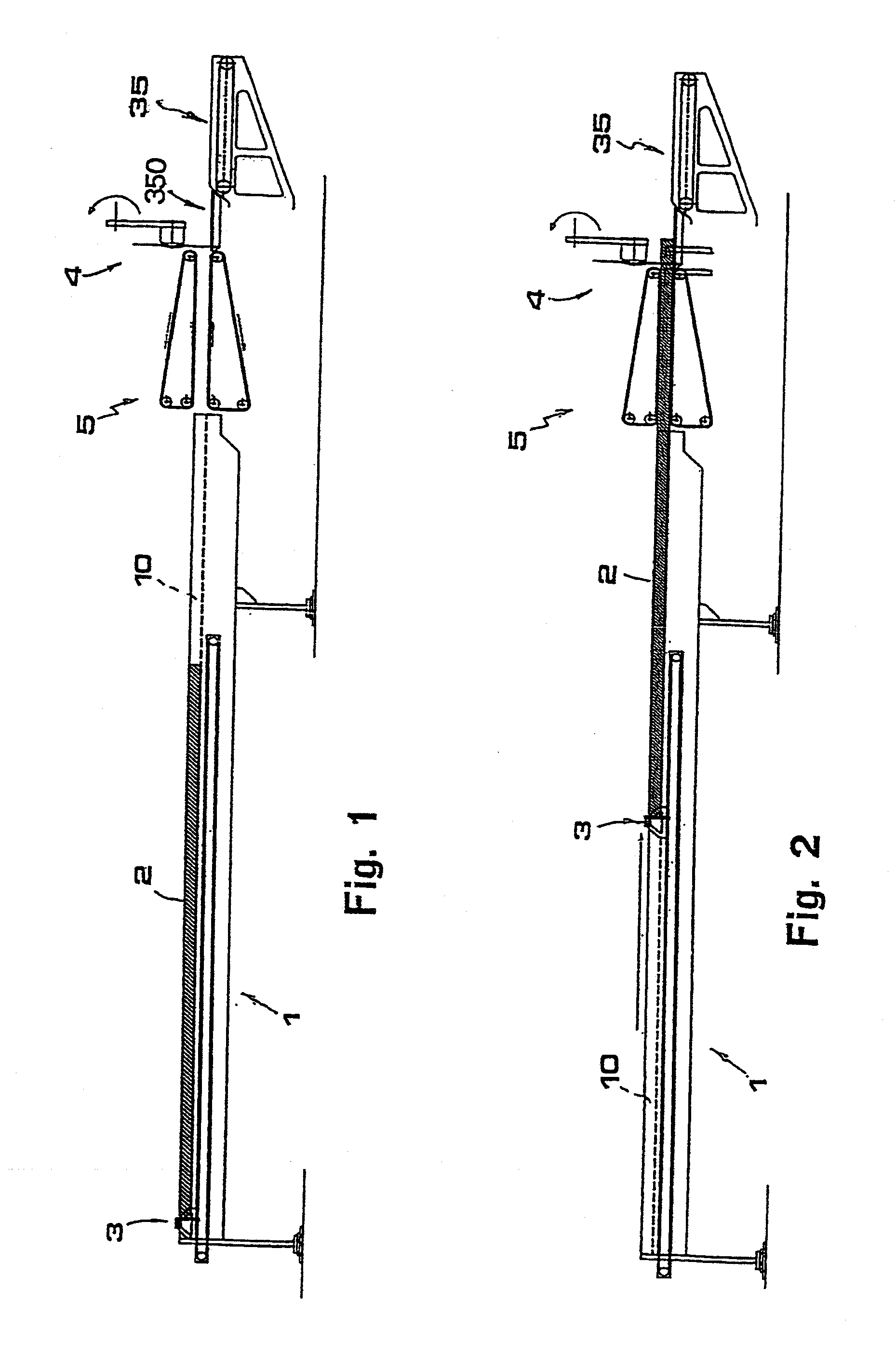
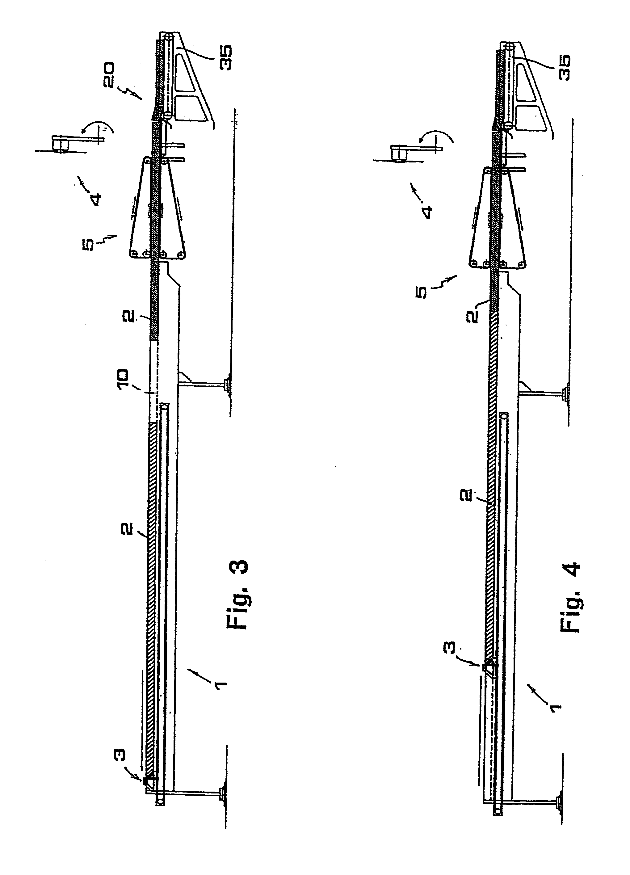
[0028]Reduced to its basic structure, and reference being made to the figures of the attached drawings, an apparatus according to the invention comprises:

[0029]a platform (1) with one or more longitudinal channels (10) inside which the logs to be cut are disposed;

[0030]pusher means (3) acting in correspondence of said platform (1) and intended for acting on the back of the logs (2) to push them, along respective guide channels (10), toward cutting means (4) disposed downstream;

[0031]clamping means (5) disposed intermediate between said pusher means (3) and said cutting means (4) and intended for engaging the logs (2) which are pushed along the channels (10) of platform (1) by the pushers (3) and driving them along as far as said cutting means (4).

[0032]Advantageously, the pusher means (3) comprise a bar (30) disposed transverse to the channels (10) of platform (1) and moved to and from the clamping means (5) by a carriage (31) associated with a corresponding electric motor (32) (sho...


PUM


Abstract

Apparatus for moving logs (2) within cutting-off machines. The apparatus includes a platform (1) with one or more longitudinal channels (10) inside which the logs to be cut are disposed, and a pusher device (3) acting in correspondence of the platform (1) and intended for acting on the back of the logs (2) to push them, along respective guide channels (10), toward a cutting device (4) disposed downstream. The apparatus includes a clamping device (5) disposed intermediate between the pusher device (3) and the cutting device (4) and intended for engaging the logs (2) which are pushed along the channels (10) of platform (1) by the pusher device (3) and driving them along up to the cutting device (4).

Description

CROSS REFERENCE TO RELATED APPLICATIONS[0001]This application is a divisional under 37 CFR 1.53(b) of pending prior application Ser. No. 10 / 547,435 filed Aug. 25, 2005 and claims the benefit under 35 U.S.C. § 119 of International Application PCT / IT 2004 / 000139 of Mar. 22, 2004, which designated inter alia the United States and which claims the priority of Italian Application FI2003A000115 of Apr. 24, 2003. The entire contents of each application is hereby incorporated by reference in its entirety.FIELD OF THE INVENTION[0002]The present invention pertains to an apparatus and a method for moving logs within cutting-off machines. In the following text, the term “logs” is meant to indicate rolls of web material (such as paper) wound up around a support core (for example, a tubular cardboard core), to be cut to form rolls of smaller length, that is, of commercial size.BACKGROUND OF THE INVENTION[0003]The production of paper rolls is known to involve cutting transversally the logs, produc...

Claims


Application Information

Patent Timeline
IPC IPC(8): B26D7/06B26D3/16B26D7/02
CPCB26D3/161B26D7/02B26D2007/013B26D7/0625B26D7/0683B26D7/0608Y10T83/0515Y10T83/04Y10T83/4792Y10T83/654Y10T83/2183Y10T83/647
Inventor PERINI
Owner PERINI
Learn More