Window shade detention member

a technology for detention members and window shades, which is applied in the direction of door/window protective devices, curtain suspension devices, draperies, etc., can solve the problems of complex management of a large number of elements, high procurement cost of elements, and complicated driving and chained moving mechanisms, etc., to achieve smooth positioning and chain-moving of window shades, simplified elements, and more versatile installation of window shades

Inactive Publication Date: 2008-07-10
LI LIN YA
View PDF10 Cites 4 Cited by
  • Summary
  • Abstract
  • Description
  • Claims
  • Application Information

AI Technical Summary

Benefits of technology

[0008]In view of the aforesaid problems, the present invention aims to provide a window shade detention member universally installable on a sliding flute of a upper beam to provide positioning and chained movement of window shades. It includes a first action side and a second action side. The first action side is located on the transverse side of the detention member and has side boards extended respectively upwards and inwards from two sides of a base board to form respectively a first trough and a second trough that form a transverse clipping trough to clip a side wing of the sliding flute of the upper beam. The first action side provides bucking for the chained movement of the window shade. The action second side is located on the longitudinal side of the detention member and has a third trough and a fourth trough on two ends of the connection junctures of the base board and the side boards to form a longitudinal clipping trough to clip another side wing of the sliding flute of the upper beam. The first action side provides lengthwise positioning, while the second action side provides bucking so that when the window shade is installed on different tracks it can be positioned as desired without skewing, and also may be chain-moved for retraction and extension. As a result positioning and chain-moving of the window shade is smoother, and the elements are simplified and can be used universally to make installation of the window shade more versatile.

Problems solved by technology

To facilitate extension and retraction of the conventional window shades a complicated driving and chained moving mechanism often is required.
Hence the number of elements increases.2. As the elements are not interchangeable, the procurement cost of the elements is higher.
Management of a great number of elements is more complicated.
Misplacement error frequently occurs on the installation site.
This affects installation operation and efficiency.

Method used


Image

  • Window shade detention member
  • Window shade detention member
  • Window shade detention member

Examples


Embodiment Construction

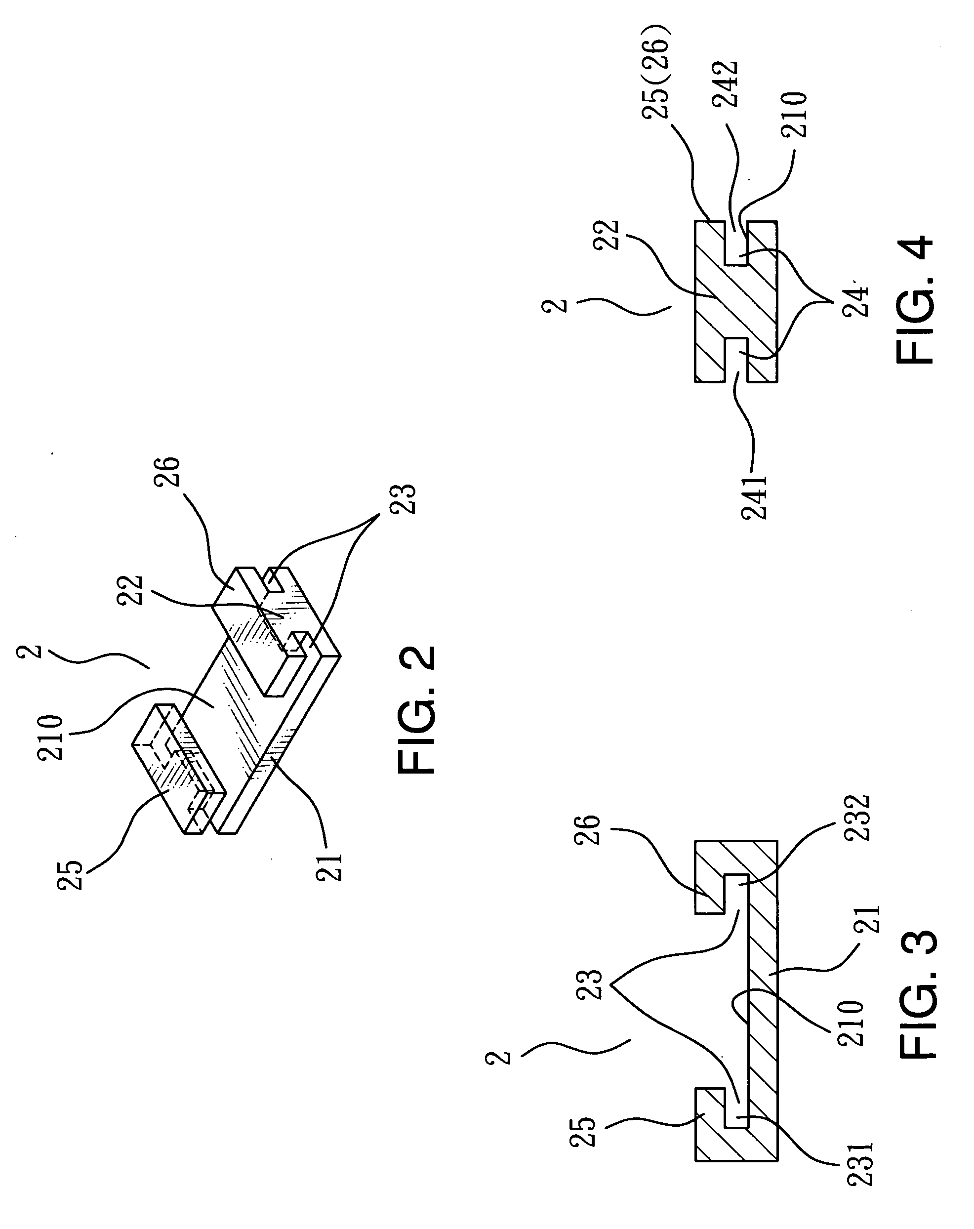
[0022]Referring to FIG. 2, the detention member 2 according to the invention includes a first action side 21 and a second action side 22 (also referring to FIGS. 2, 3 and 4).

[0023]The first action side 21 is located a transverse side of the detention member 2 (referring to FIG. 3) and has side boards 25 and 26 extended upwards and inwards from two sides of a base board 210 to form a first trough 231 and a second trough 232 between the side boards 25 and 26 and the base board 210 that correspond to each other and form a transverse clipping trough 23.

[0024]The second action side 22 is located on a longitudinal side of the detention member 2 (referring to FIG. 4).

[0025]In order to make a window shade universally installable on different tracks, the second action side 22 has a third trough 241 and a fourth trough 242 on two ends at the connection junctures of the base board 210 and the side boards 25 and 26 that correspond to each other and form a longitudinal clipping trough 24 (referr...


PUM


Abstract

A window shade detention member universally installable on a sliding flute of a upper beam to provide positioning and chained movement for window shades includes a first action side and a second action side. The first action side is located on a transverse side of a detention member and has side boards extended upwards and inwards from two sides of a base board to form a first trough and a second trough that form a transverse clipping trough which clips side wings of the sliding flute of the upper beam. The first action side also provides bucking for the chained movement of the window shades. The second action side is located on a longitudinal side of the detention member and has a third trough and a fourth trough on two ends of the connection junctures of the base board and side boards to form a longitudinal clipping trough. The longitudinal clipping trough clips the side wings of the sliding flute of the upper beam. The first action side provides lengthwise constraint while the second action side provide bucking so that the window shade can be installed on different tracks and confined without skewing. Chained movement of retraction and extension of the window shade can be done smoothly. The elements are simplified and universally applicable. Installation of the window shade is more flexible and versatile.

Description

BACKGROUND OF THE INVENTION[0001]1. Field of the Invention[0002]The present invention relates to a window shade detention member and particularly to a detention member universally installable on a sliding flute of a upper beam to provide positioning and chained movement of a window shade, and universal and simplified structural elements and versatile installation of the window shade.[0003]2. Description of the Prior Art[0004]Many types of window shades are now available on the market. They are widely used in houses to enhance the appeal of interior design. To facilitate extension and retraction of the conventional window shades a complicated driving and chained moving mechanism often is required. To remedy this problem Applicant has proposed a technique disclosed in Taiwan patent publication No. M294283. However use of window shades is more versatile nowadays. Aside from installing on the same sliding flute and track, each window shade may also be installed on different tracks to cr...

Claims


Application Information

Patent Timeline
Patent Type & Authority Applications(United States)
IPC IPC(8): E06B9/322
CPCA47H23/04E06B9/36A47H2023/025A47H2001/047
Inventor LI, LIN YA
Owner LI LIN YA
Why Eureka
Try Eureka