
Cigarette box and an outer blank therefor

Inactive Publication Date: 2008-07-10
JAPAN TOBACCO INC
View PDF17 Cites 7 Cited by
  • Summary
  • Abstract
  • Description
  • Claims
  • Application Information

AI Technical Summary

Benefits of technology

[0011]Preferably, the rear wall of the box body has a concave that enlarges the pocket space. This concave reduces an outward bulge of the annex wall when the sheet-like article is contained in the pocket. The cigarette box then has the rear face that is virtually flat, so that the cigarette box does not get stuck in a vending machine when dispensed from the machine. Consequently, the cigarette box is stably dispensed from the vending machine.
[0014]Preferably, the mouth of the pocket has a shape of a cove that is dented concave toward the bottom of the box body. Such a pocket mouth allows an access to the sheet-like article contained in the pocket and facilitates a removal of the article from the pocket.
[0015]More specifically, the sheet-like article is preferably a pouch that is usable as an ash container. The pouch is removed from the pocket prior to smoking and is used as an ash container. After smoking, ashes and butts in the pouch are eliminated. The pouch is then put back into the pocket of the cigarette box and is carried with the cigarette box by the smoker.

Problems solved by technology

However, it is too much bother for a smoker to take along the portable ash container, albeit a small one, in addition to the cigarette box.
On top of that, a used portable ash container gives off an offensive smell, so that it is unfavorable to put the used container back into the cigarette box.

Method used


Image

  • Cigarette box and an outer blank therefor
  • Cigarette box and an outer blank therefor
  • Cigarette box and an outer blank therefor

Examples


first embodiment

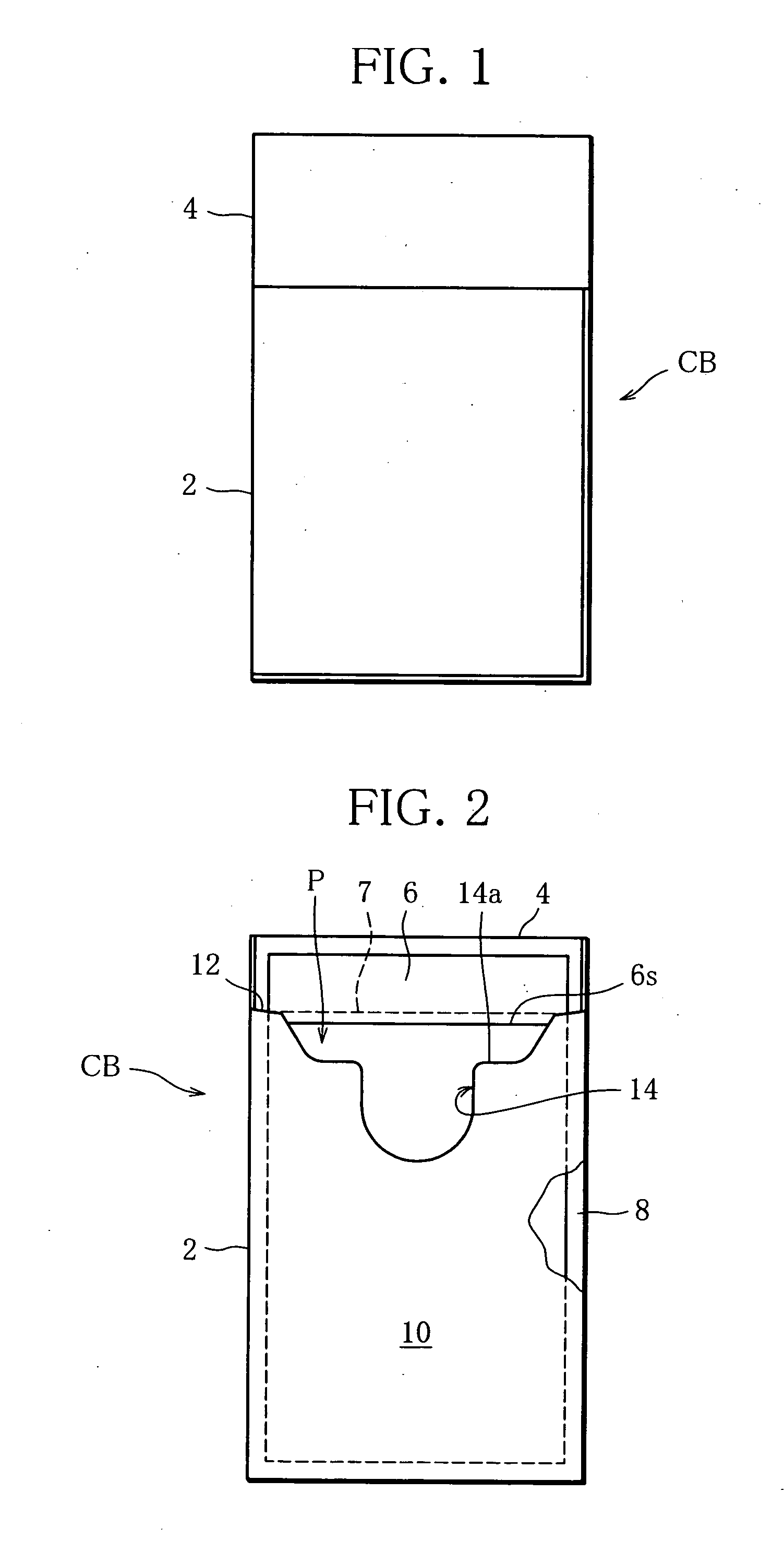
[0032]Referring to FIG. 1, a cigarette box CB of a first embodiment is called a hinged-lid package and is a rectangular parallelepiped with a longitudinal axis. The cigarette box CB contains an inner pack, not shown. The inner pack includes a bundle of filter cigarettes or cigarettes and a wrapping material that wraps the bundle.

[0033]The cigarette box CB is wrapped in a transparent film, not shown, which has a tear tape.

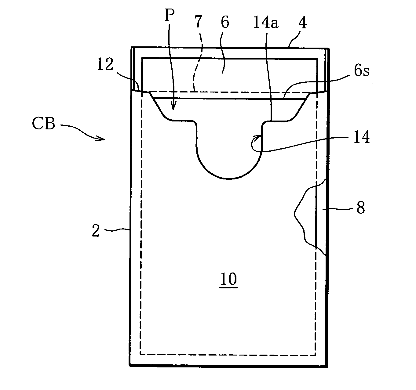
[0034]The cigarette box CB includes a box body 2 having an open upper end and a box-shaped lid 4 that opens / closes the upper end of the box body 2. The lid 4 is connected to a back face of the box body 2 across a hinge, or a self hinge. The lid 4 rotates around the self hinge to open / close the upper end, namely the opening, of the box body 2.

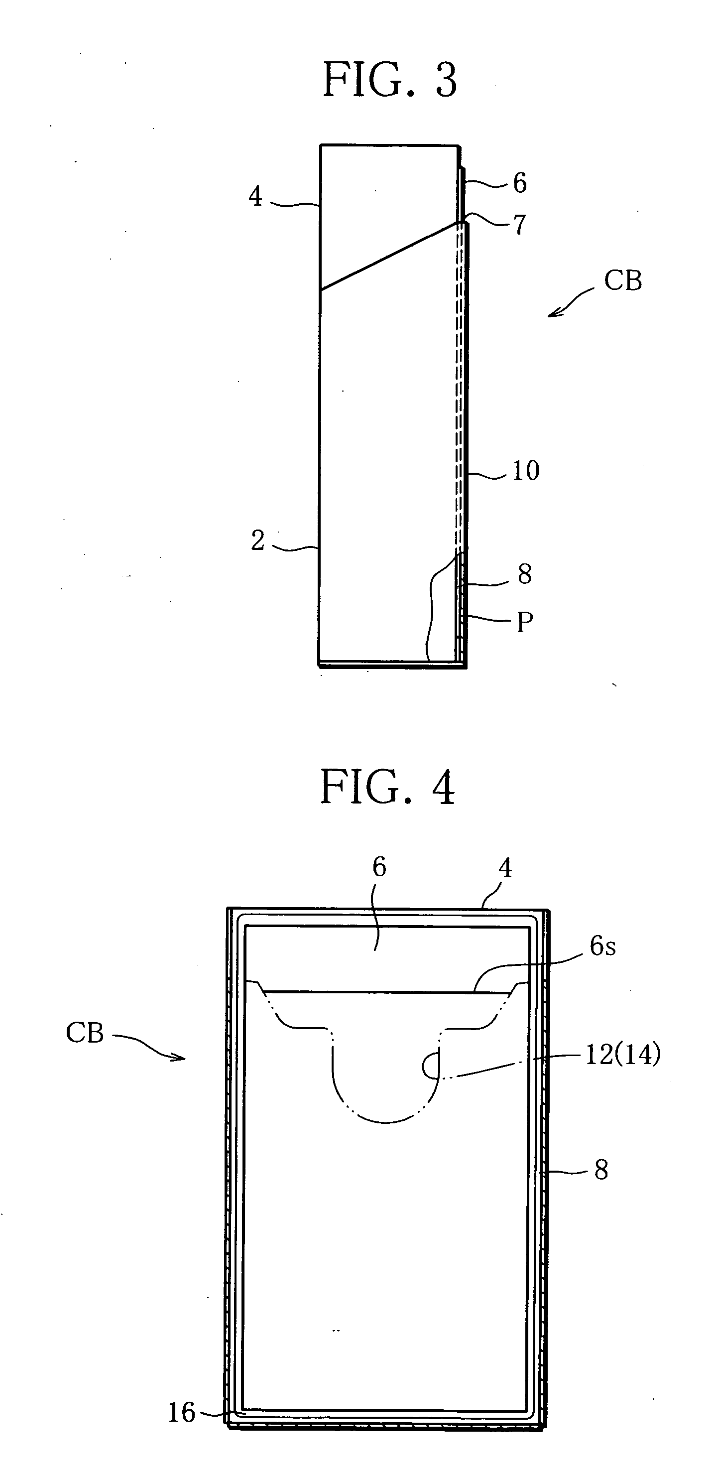
[0035]As illustrated in FIGS. 2 and 3, the box body 2 holds at least one sheet-like article, for example, a rectangular sheet-like pouch 6 serving as an ash container. The pouch 6 has flexibility and is situated on the back face...

second embodiment

[0068]FIGS. 12 and 13 show an outer blank according to a

[0069]The outer blank of the second embodiment includes a main part 18′ shown in FIG. 12 and a sub-part 20′ in FIG. 13. The main part 18′ has panels and flaps similar to those of the main section 18, except middle side flaps 32a are located on both sides of a front panel 28. This means that the main part 18′ corresponds to a blank for fabricating a conventional hinged-lid package. The sub-part 20′ simply includes outer side flaps 56 in both sides of an outer rear panel 54, and differs from the subsection 20.

[0070]In FIGS. 12 and 13, the panels and flaps corresponding to those in FIG. 7 are provided with the same respective reference numerals.

[0071]The main part 18′ of FIG. 12 is folded around an inner pack IP having an inner frame IF in a well-known manner, thereby forming a cigarette box CB′. Thereafter, as illustrated in FIG. 13, at least one pouch 6 is placed in a concave 16 formed in a rear face of the cigarette box CB′. Th...


PUM

PropertyMeasurementUnit
Sizeaaaaaaaaaa
Shapeaaaaaaaaaa
Depthaaaaaaaaaa

Abstract

A cigarette box has a box body (2), a lid (4) that opens / closes the box body (2), an outer wall (10) superposed on a rear wall of the box body (2) and forms a pocket (P) in cooperation with the rear wall, and a sheet-like pouch (6) removably contained in the pocket (P), the pouch (6) being used as a portable ash container.

Description

TECHNICAL FIELD[0001]The present invention relates to a cigarette box and an outer blank for fabricating the cigarette box, and more specifically, to a cigarette box capable of containing at least one sheet-like article and an outer blank therefor.BACKGROUND ART[0002]As cigarette boxes of this type, hinged-lid cigarette boxes have widely been used. Such cigarette boxes each contain an inner pack. The inner pack includes a cigarette bundle and a wrapping material that wraps the bundle.[0003]Well known among the above-mentioned cigarette boxes are those that each contain a sheet-like article, or a coupon, together with the inner pack. A cigarette box of this type is disclosed, for example, in Unexamined Japanese Patent Publication No. 8-253279. When the cigarette box disclosed in this publication is opened, a coupon protrudes from the cigarette box.[0004]There is a tendency in recent years that many of public spaces are designated as non-smoking areas. Accordingly, smoking areas in wh...

Claims


Application Information

Patent Timeline
IPC IPC(8): B65D85/10B65D85/00B65D5/66
CPCA24F19/0028A24F19/0064B65D2209/00B65D85/10B65D5/6691B65D85/1081B65D85/1045B65D5/44A24F19/10
Inventor TOSAKA, MASAHIKONAKAMURA, TETSUYA
Owner JAPAN TOBACCO INC
Features
  • Generate Ideas
  • Intellectual Property
  • Life Sciences
  • Materials
  • Tech Scout
  • Unparalleled Data Quality
  • Higher Quality Content
  • 60% Fewer Hallucinations
Learn More