
LPG tank and cart therefor

a technology of liquid storage tanks and carts, applied in the direction of hand cart accessories, supporting parts, sledges, etc., can solve the problem of not always having a 2-wheeled dolly availabl

Inactive Publication Date: 2008-07-10
BISHAMON IND
View PDF29 Cites 4 Cited by
  • Summary
  • Abstract
  • Description
  • Claims
  • Application Information

AI Technical Summary

Benefits of technology

[0006]One aspect of the invention resides in a carriage. The carriage comprises a gripping member defining an opening for receipt of a selected part of an article to be gripped. The gripping member extends circumferentially of the opening and is elastically deformable between an expanded condition and a contracted condition. The opening has a first size in the expanded condition which is sufficiently large for the selected part of the article to enter the opening, and the opening has a second size smaller than the first size in the contracted condition. The second size is selected such that the gripping member grips the selected part of the article when the selected part is received in the opening and the gripping member is in the contracted condition. The carriage further comprises at least one rolling member, e.g., a wheel or caster, and means for rotatably mounting the rolling member on the gripping member.

Problems solved by technology

Although the tanks can be carried manually, this can be cumbersome.
However, a 2-wheeled dolly is not always available when a tank runs dry.

Method used


Image

  • LPG tank and cart therefor
  • LPG tank and cart therefor
  • LPG tank and cart therefor

Examples


Embodiment Construction

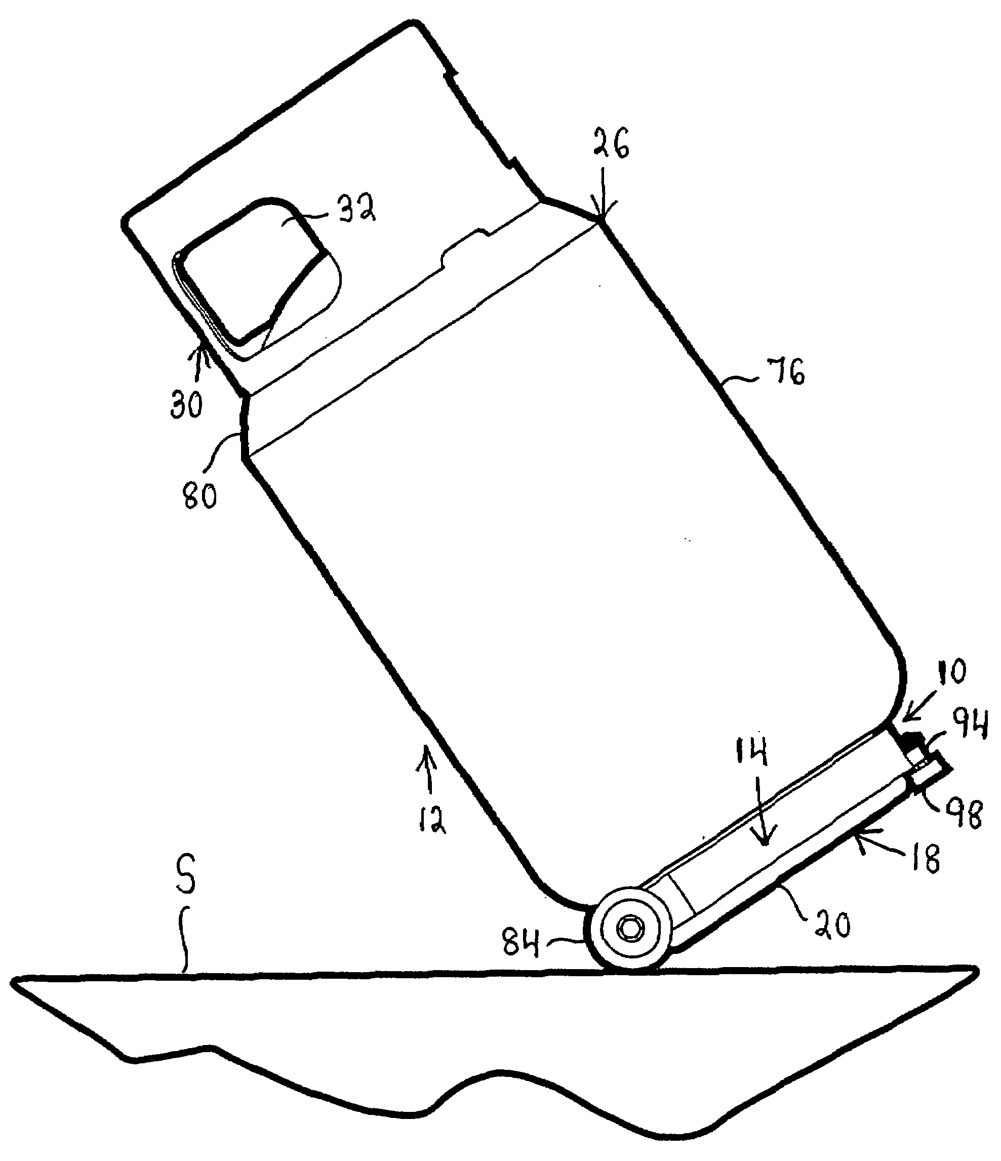
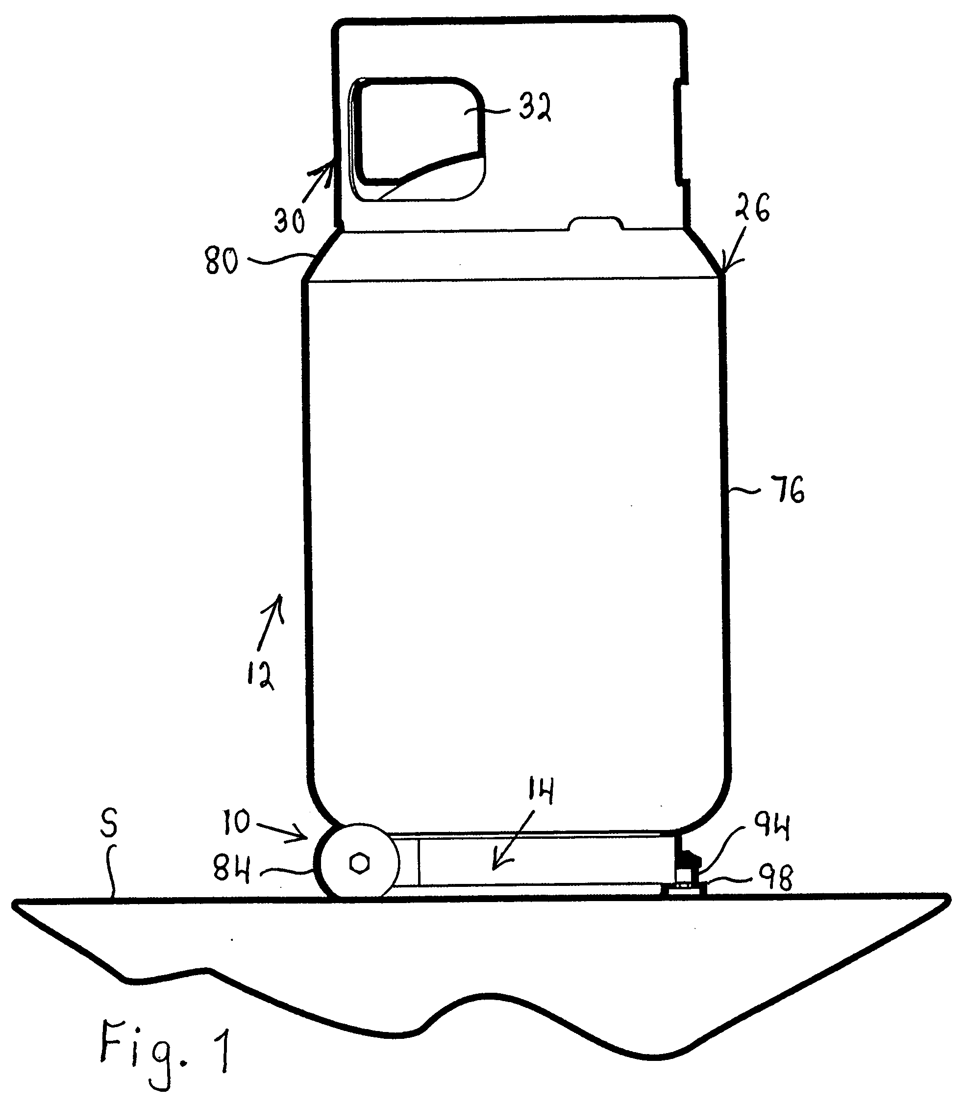
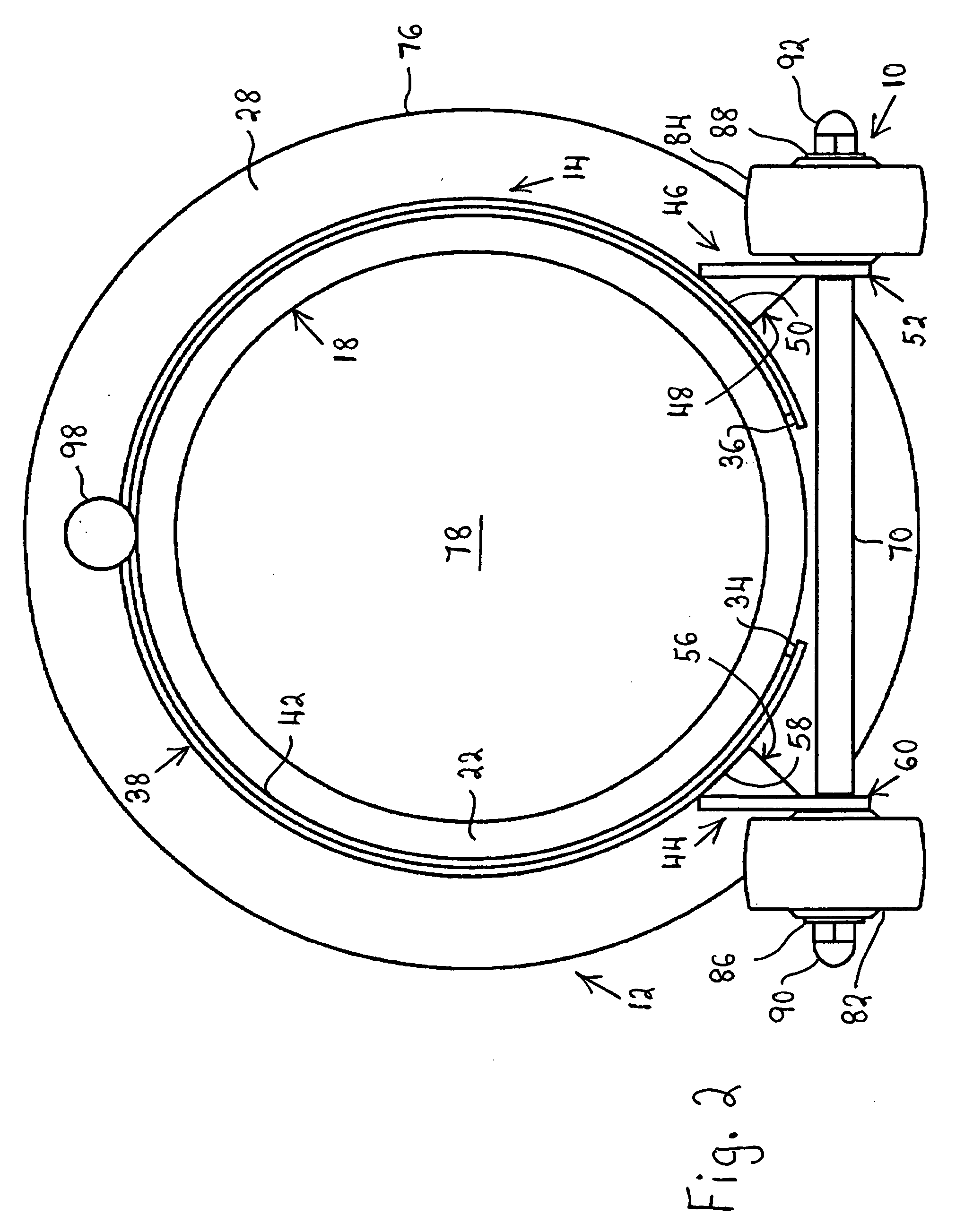
[0036]Referring to FIGS. 1 and 2, the numeral 10 identifies a cart or carriage in accordance with the invention. The cart 10 is secured to an elongated container or vessel 12 which accommodates fluid under pressure, and the container or vessel 12 is assumed to be a conventional tank for liquid propane gas. The tank 12 is here of the type used to fuel vehicles, e.g., forklifts. The cart 10 is designed for manual transportation of the tank 12.

[0037]Considering FIG. 3 in conjunction with FIGS. 1 and 2, the cart 10 includes a clamping member or gripping member 14 in the form of a band or a strip. The clamping member 14 is elastically or resiliently deformable between an expanded condition shown in FIG. 3 and a contracted condition shown in FIGS. 1 and 2. The terms “elastically deformable” and “resiliently deformable” mean that the clamping member 14 can undergo deformation discernible by the human senses without the aid of instruments and thereafter return to its condition preceding def...


PUM


Abstract

A cart is clamped to a tank for liquid propane gas and has a height which is a minor fraction of the height of the tank. In projections of the cart and the carriage on a plane normal to the longitudinal axis of the tank, no more than a minor fraction of the projection of the cart is located outside the projection of the tank.

Description

BACKGROUND OF THE INVENTION[0001]1. Field of the Invention[0002]The invention relates to the handling of containers for fluid.[0003]2. Description of the Prior Art[0004]Forklift trucks are fueled by tanks of liquid propane gas (LPG) which are placed in cradles mounted on the trucks. When a tank runs dry, the tank is replaced by a full tank. The dry tank is taken to a storage location of the facility in which the forklift trucks operate, and the dry tank is subsequently trucked from this storage location to a facility for refilling tanks of this type. The refilled tank is returned to the storage location to await renewed use.[0005]There is usually no warning when a tank runs dry, and the forklift truck on which the tank is mounted will generally not be at the storage location when this occurs. It is then necessary to transport the dry tank from the forklift truck to the storage location and to transport a full tank from the storage location to the forklift truck. Although the tanks c...

Claims


Application Information

Patent Timeline
Patent Type & Authority Applications(United States)
IPC IPC(8): B62B1/00
CPCB62B1/008B62B1/12B62B2203/44B62B5/0083B62B2202/022B62B1/264
Inventor STONE, ROBERT M.
Owner BISHAMON IND
Learn More