Fuel supplying system of lpi engine

A technology of fuel supply system and liquid propane, which is applied in the direction of liquid fuel feeder, charging system, engine components, etc., and can solve problems such as long waiting time for customers, weakened durability of fuel pumps, and customer complaints

Inactive Publication Date: 2011-03-30
HYUNDAI MOTOR CO LTD
View PDF1 Cites 3 Cited by
  • Summary
  • Abstract
  • Description
  • Claims
  • Application Information

AI Technical Summary

Problems solved by technology

[0011] However, since the conventional LPI fuel pump is installed inside the LPI tank for supplying fuel to the engine, in the event of failure of the fuel pump, after a gas extractor extracts high-pressure LPG fuel from the tank, it must be The tank was cut to replace the pump and the tank should be repaired afterwards
[0012] In this case, gas extraction is only allowed in designated establishments that comply with safety restrictions, resulting in long waits for customers
[0013] As a result, manpower for pumping gas is increased, causing complaints from customers, especially taxi drivers
[0014] Additionally, parts and material costs to compensate for fuel pump noise, vibration and vibration (NVH) repairs are expensive
[0015] In addition, since many parts are welded inside the fuel tank, thermal deformation of the fuel tank plate is caused, and scale is generated during the welding process that deteriorates the durability of the fuel pump.
[0016] Also, the problem is that repairs and inspections of LPI tanks are avoided by field workers due to safety concerns and discomfort caused by inhaling the gas

Method used


Image

  • Fuel supplying system of lpi engine
  • Fuel supplying system of lpi engine
  • Fuel supplying system of lpi engine

Examples


Embodiment Construction

[0031] Reference will now be made in detail to various embodiments of the invention, examples of which are illustrated in the accompanying drawings and described below. While the invention will be described in conjunction with exemplary embodiments, it will be appreciated that present description is not intended to limit the invention to those exemplary embodiments. On the contrary, the invention is intended to cover not only the exemplary embodiments but also various alternatives, modifications, equivalents and others which may be included within the spirit and scope of the invention as defined by the appended claims. implementation.

[0032] Exemplary embodiments of the present invention will be described in detail below with reference to the accompanying drawings.

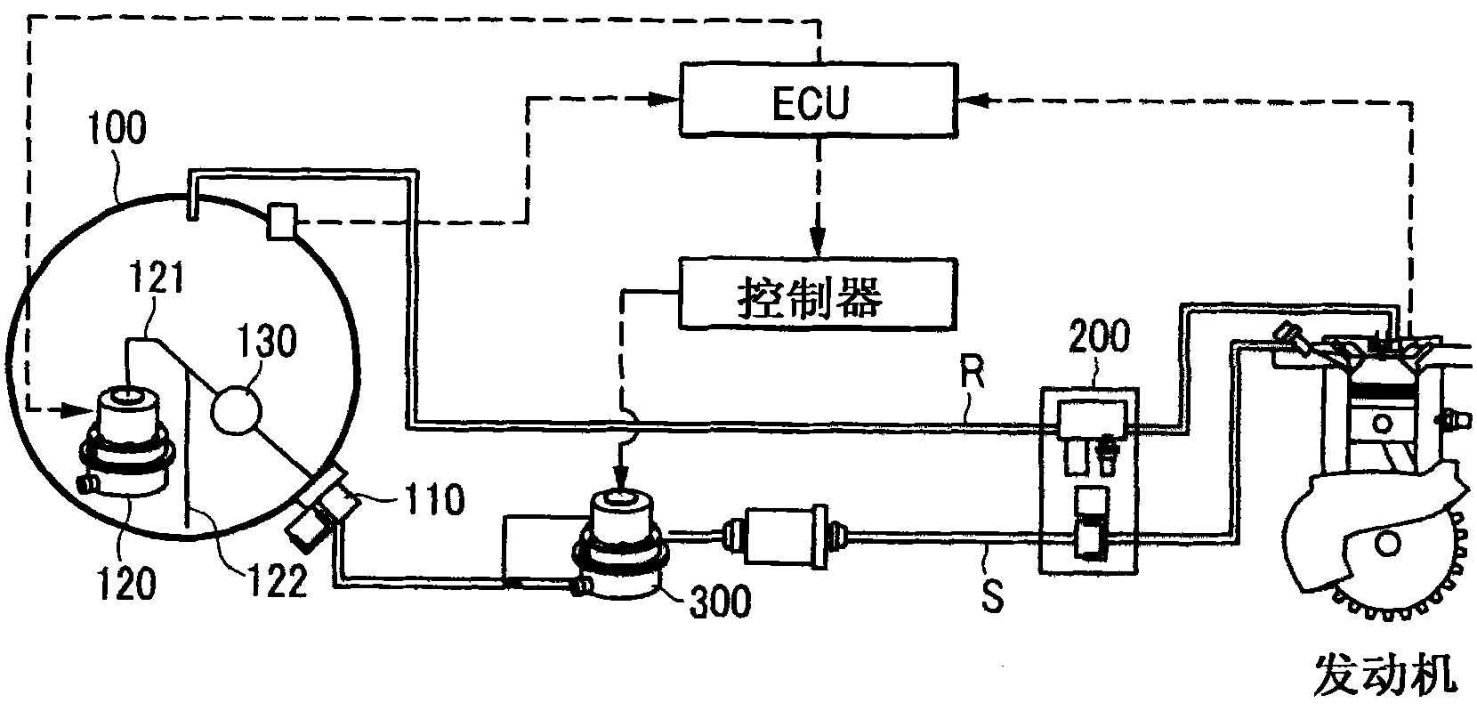
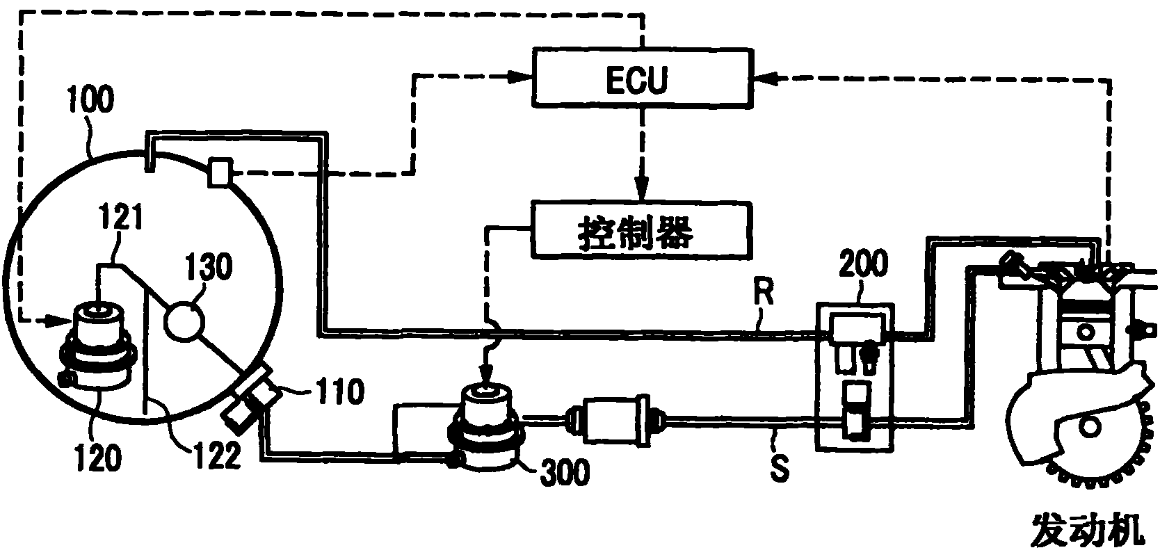
[0033] figure 1 is a schematic diagram showing a fuel supply system of a liquid propane fuel (LPI) engine according to an exemplary embodiment of the present invention.

[0034] Such as figure 1 As shown, ...


PUM


Abstract

A fuel supplying system of a liquid propane injection (LPI) engine, may include a fuel tank for storing fuel, a main fuel pump connected to the fuel tank and disposed at the exterior of the fuel tank, a fuel supply line connecting the main fuel pump and the engine to supply fuel from the main fuel pump to the engine, and a fuel return line connecting the engine and the interior of the fuel tank to return fuel from the engine to the interior of the fuel tank, wherein a sub-fuel pump is provided to the interior of the fuel tank and connected to the fuel supply line through a sub-fuel pump connecting pipe, the sub-fuel pump being operated when a predetermined condition is satisfied.

Description

[0001] Cross References to Related Applications [0002] This application claims priority from Korean Patent Application No. 10-2009-0079450 filed on Aug. 26, 2009, the entire contents of which are hereby incorporated by reference for all purposes. technical field [0003] The present invention relates to a fuel supply system for a liquid propane injection (LPI) engine, and more particularly, to a fuel supply system for an LPI engine, which can improve maintenance performance and serviceability. Background technique [0004] The LPI engine includes an LPI fuel pump supplying fuel therein, thereby achieving stability in fuel supply performance when fuel is forcibly supplied thereinto. [0005] That is, the fuel pump is installed inside the fuel tank, and the forcibly supplied liquid LPG fuel is injected by the injector. [0006] The LPI engine is adapted to correspond to strict emission control, and can improve the start of the engine in winter while reducing the injection o...

Claims


Application Information

Patent Timeline
Patent Type & Authority Applications(China)
IPC IPC(8): F02M21/02
CPCF02M37/0052F02M37/0029F02M21/02F02M37/00F02M37/18
Inventor 宋柱泰
Owner HYUNDAI MOTOR CO LTD
Why Eureka
Try Eureka