
Battery Temperature Regulating System And Method For An Electric Vehicle, Battery Housing Box For An Electric Vehicle, And Vehicle Incorporating Same

a technology for electric vehicles and temperature regulation systems, which is applied in secondary cell servicing/maintenance, cell components, cycle equipments, etc., can solve problems such as battery performance deterioration, and achieve the effect of simple structure and enhanced maintainability and assembly of the lid body member

Inactive Publication Date: 2010-07-01
HONDA MOTOR CO LTD
View PDF13 Cites 74 Cited by
  • Summary
  • Abstract
  • Description
  • Claims
  • Application Information

AI Technical Summary

Benefits of technology

[0023]The present invention is capable of cooling or heating (i.e., regulating the temperature of) the battery by controlling the first air flow control valve and the second air flow control valve to control the flow of the air flowing in the housing box. Accordingly the present invention is capable of regulating the temperature of the battery to an appropriate (operable) temperature.
[0024]In addition, the present invention enhances the maintainability and assemblability of the lid body member, because the present invention collectively includes, in the lid body member, all the component parts concerning the control of the flow of the air. Furthermore, the present invention is capable of constructing the main housing body with a simpler structure.
[0025]Moreover, the present invention is capable of adjusting the flow of the air inside the housing box depending on the temperature of the inside of the housing box, and is accordingly capable of adjusting the temperature of the battery appropriately.
[0026]Besides, the present invention is capable of controlling the air flow rate of the fan depending on the temperature of the inside of the housing box, and is accordingly capable of adjusting the temperature of the battery appropriately.
[0027]As well, the present invention is capable of cooling the battery whose temperature becomes higher by use of the air taken in through the inlet ports.
[0028]Also, the present invention is capable of causing the air heated by use of heat produced by the battery and the like to stay inside the housing box, and is accordingly capable of heating the battery whose temperature becomes lower by use of the heated air.

Problems solved by technology

In general, however, it is likely that the battery may deteriorate its performance when the temperature of battery falls.

Method used


Image

  • Battery Temperature Regulating System And Method For An Electric Vehicle, Battery Housing Box For An Electric Vehicle, And Vehicle Incorporating Same
  • Battery Temperature Regulating System And Method For An Electric Vehicle, Battery Housing Box For An Electric Vehicle, And Vehicle Incorporating Same
  • Battery Temperature Regulating System And Method For An Electric Vehicle, Battery Housing Box For An Electric Vehicle, And Vehicle Incorporating Same

Examples


Embodiment Construction

[0039]A specific illustrative embodiment of the present invention will now be described, with reference to the drawings. Throughout this description, relative terms like “upper”, “lower”, “above”, “below”, “front”, “back”, and the like are used in reference to a vantage point of an operator of the vehicle, seated on the driver's seat and facing forward. It should be understood that these terms are used for purposes of illustration, and are not intended to limit the invention.

[0040]Now, referring to the drawings, a saddle-ridding type electric vehicle according to an illustrative embodiment of the present invention is described. Again, in the following description, upward, downward, frontward, rearward, leftward and rightward indicate directions viewed from the vantage point of a driver.

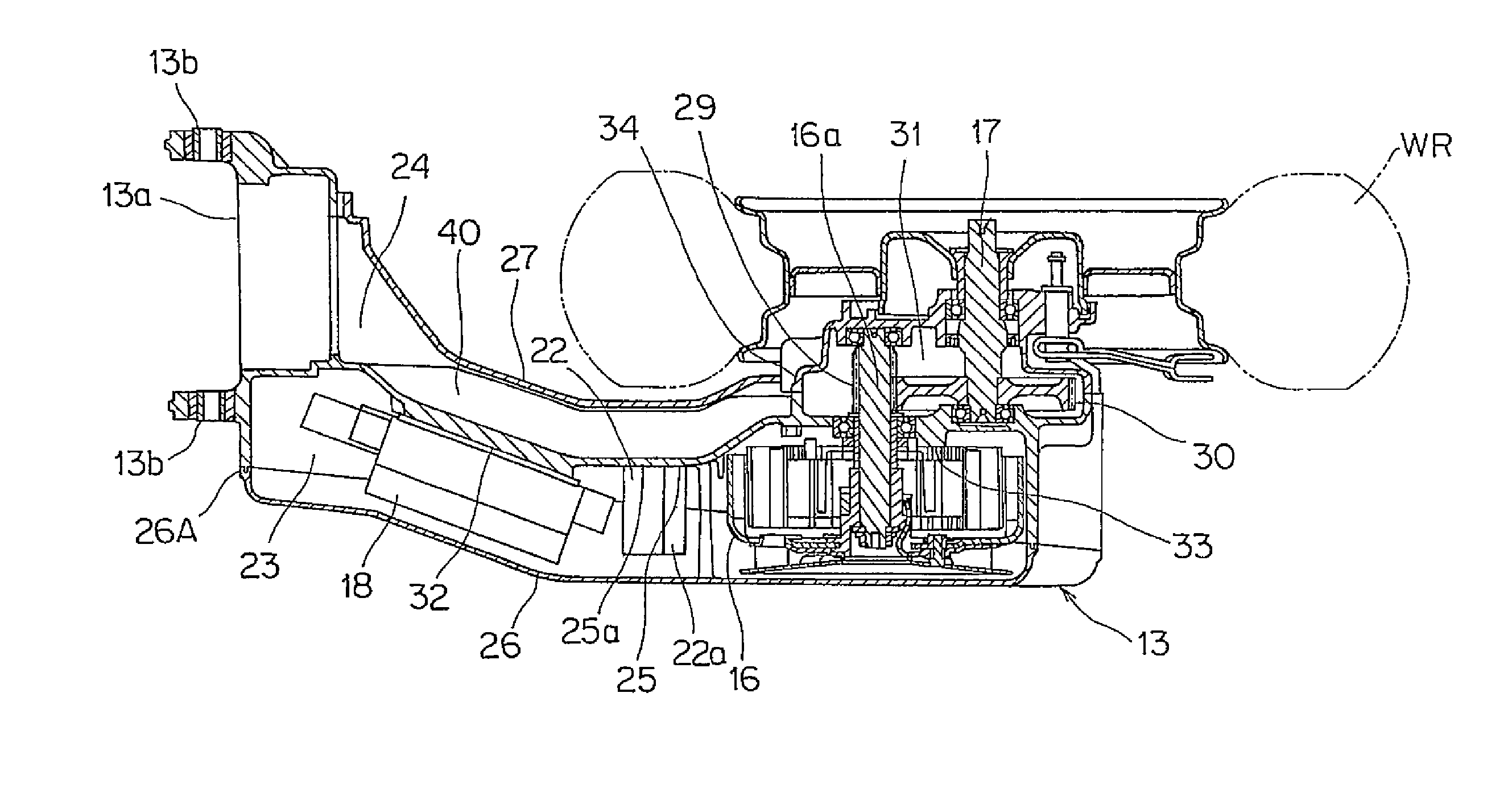
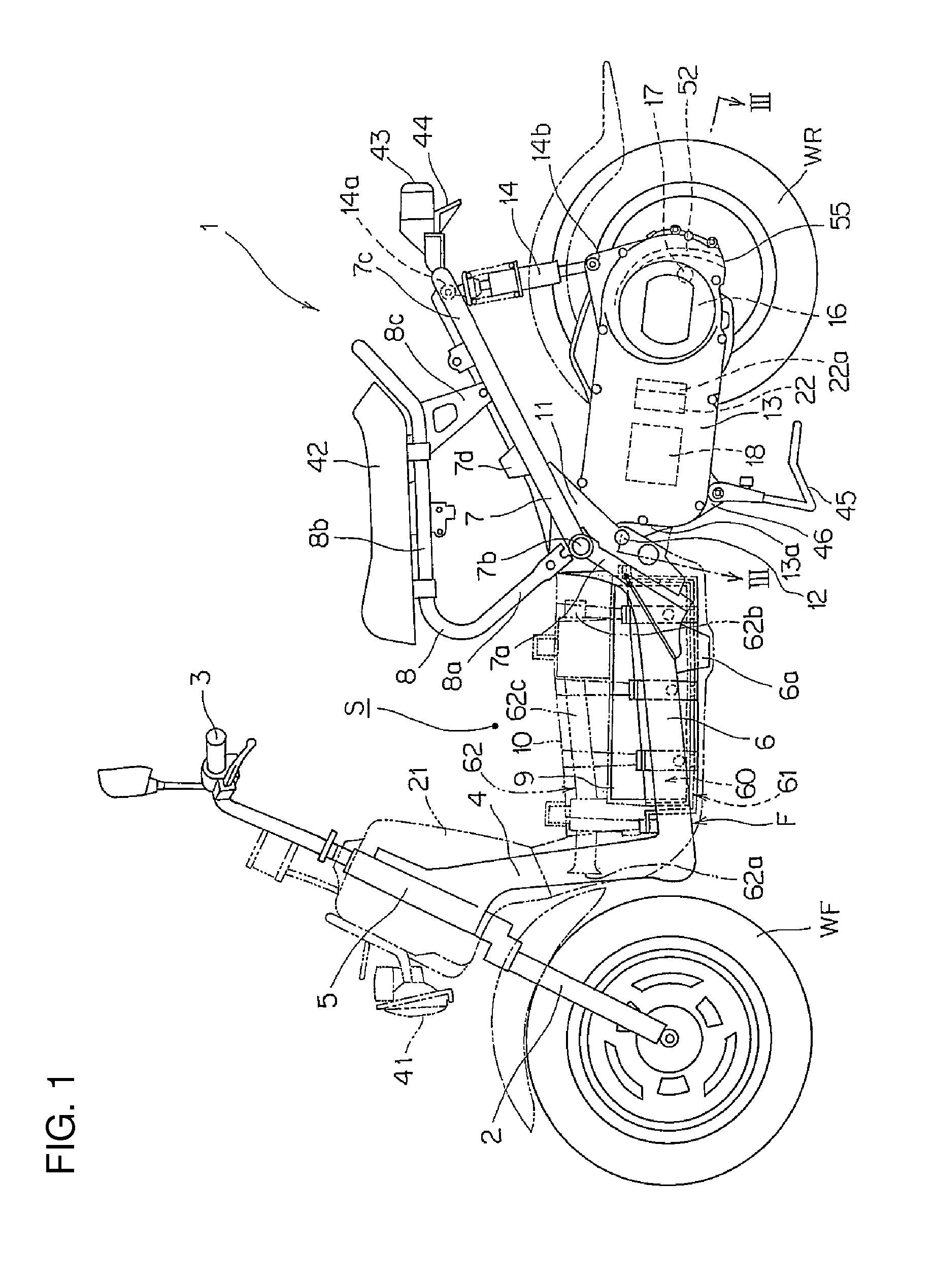
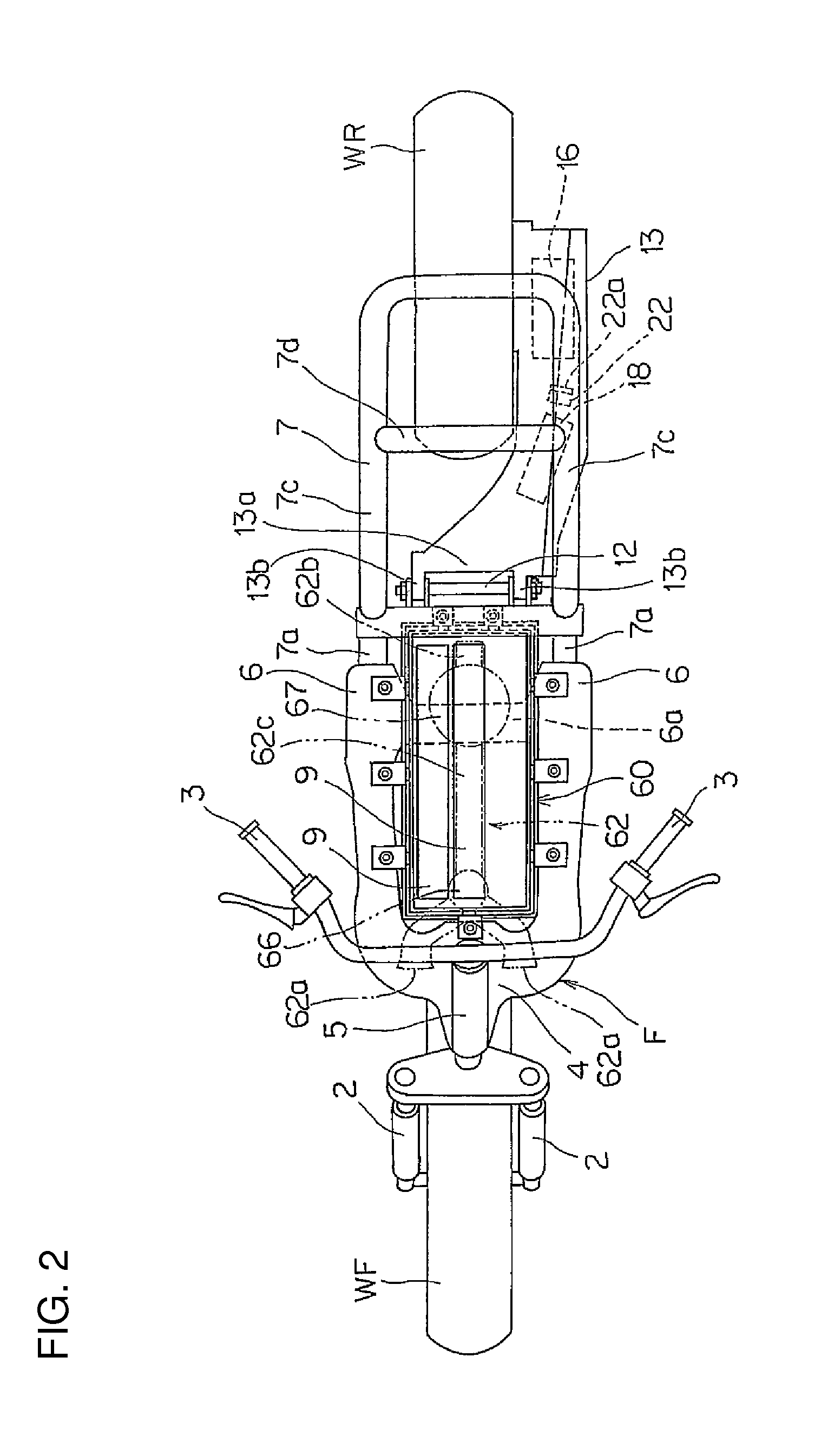
[0041]FIG. 1 is a side view of the saddle-riding type electric vehicle according to the embodiment of the present invention. FIG. 2 is a top plan view of the saddle-riding type electric vehicle. It ma...


PUM

PropertyMeasurementUnit
areaaaaaaaaaaa
temperatureaaaaaaaaaa
air flow rateaaaaaaaaaa

Abstract

A battery housing structure, in an electric vehicle, is operable to regulate a temperature of a battery disposed between front and rear wheels of the vehicle. The battery housing structure includes a main housing body for receiving the battery, inlet and outlet ports for respectively supplying air to and discharging air from the main housing body; and a fan for discharging air from the main housing body. A bypass passage is provided in the battery housing structure for selectively connecting a downstream side of the fan with the inlet ports. First and second air flow control valves are also provided in the battery housing structure for selectively controlling and routing the flow of air within the battery housing structure.

Description

CROSS-REFERENCE TO RELATED APPLICATIONS[0001]The present invention claims priority under 35 USC 119 based on Japanese patent application No. 2008-332329, filed on Dec. 26, 2008. The entire subject matter of this priority document, including specification claims and drawings thereof, is incorporated by reference herein.BACKGROUND OF THE INVENTION[0002]1. Field of the Invention[0003]The present invention relates to a battery temperature control system and method for regulating battery temperatures in a saddle-riding type electric vehicle, and to a vehicle including the described battery temperature control system. More particularly, the present invention relates to a battery temperature control system and method in which a controller cooperates with a battery housing structure to regulate the temperature of batteries stored therein, during operation of a saddle-riding type electric vehicle, and to a vehicle incorporating the temperature control system.[0004]2. Background Art[0005]Ther...

Claims


Application Information

Patent Timeline
Patent Type & Authority Applications(United States)
IPC IPC(8): B60R16/04H01M10/50B62J9/00B62J99/00H01M50/204H01M50/249H01M50/271
CPCB60K1/04B60L50/66B60L3/0046B60L2200/12B60Y2200/126B62K11/10B62K19/30B62K25/283B62K25/32B62K2204/00H01M2/1072H01M10/425H01M10/48Y02T10/7005Y02T10/705Y02T90/16B60Y2200/12H01M10/625H01M10/615H01M10/635H01M10/6565H01M10/6566H01M10/613B60L58/26B60L58/27B60K2001/005Y02T10/70Y02E60/10B62J50/30H01M50/204H01M50/249B60L50/64H01M50/271
Inventor TAKAMURA, TOSHIAKIOTSU, ATSUSHISONE, TAKASHI
Owner HONDA MOTOR CO LTD
Learn More