Eureka AIR delivers breakthrough ideas for toughest innovation challenges, trusted by R&D personnel around the world.

Apparatus and Methods to Measure Economizer Outdoor Air Fractions and Fault Detection Diagnostics of Airflow, Cooling Capacity, and Heating Capacity

a technology of outdoor air fraction and economizer, applied in the field of fault detection of airflow, cooling capacity, and heating capacity, can solve the problems of increasing carbon dioxide emissions contributing to global warming, and the accuracy of oaf measurements made at lower temperature differences is slightly lower

Active Publication Date: 2017-11-30
MOWRIS ROBERT J
View PDF5 Cites 43 Cited by
  • Summary
  • Abstract
  • Description
  • Claims
  • Application Information

AI Technical Summary

Benefits of technology

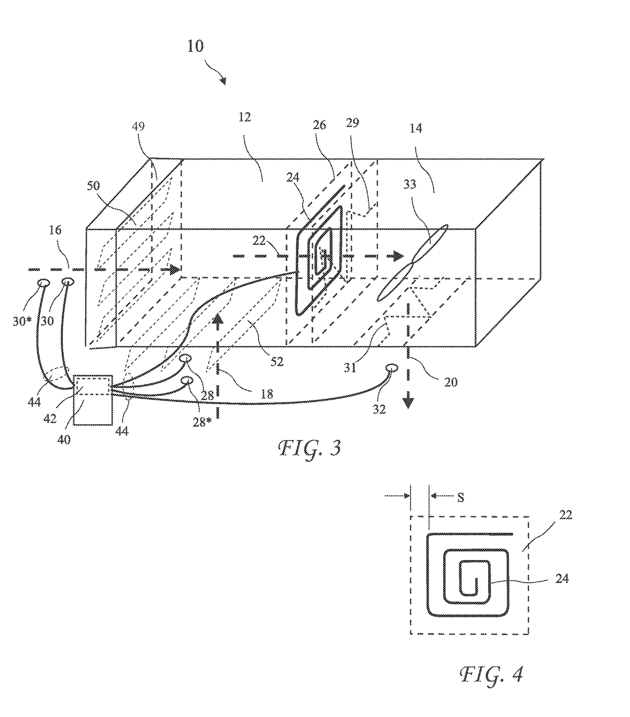
The invention provides a method for accurately measuring mixed air temperature in an HVAC system by positioning an averaging temperature sensor in the passage between the mixed air chamber and the air conditioner evaporator and furnace / heat exchanger. The sensor is formed into a flat spiral shape to measure the average temperature of air flowing through the mixed-air chamber. The method also involves using sensors to transmit temperature or humidity measurement data to a device or controller, which calculates the measured outdoor airflow based on regulatory requirements and adjusts the damper position to provide an optimally minimum damper position to achieve the required outdoor airflow.

Problems solved by technology

An outdoor airflow exceeding the American Society of Heating Refrigeration and Air-Conditioning Engineers (ASHRAE) Standard 62.1 minimum outdoor air requirements wastes space cooling and heating energy and increases carbon dioxide emissions contributing to global warming.
OAF measurements made at lower temperature differences will have slightly lower accuracy.

Method used


Image

  • Apparatus and Methods to Measure Economizer Outdoor Air Fractions and Fault Detection Diagnostics of Airflow, Cooling Capacity, and Heating Capacity
  • Apparatus and Methods to Measure Economizer Outdoor Air Fractions and Fault Detection Diagnostics of Airflow, Cooling Capacity, and Heating Capacity
  • Apparatus and Methods to Measure Economizer Outdoor Air Fractions and Fault Detection Diagnostics of Airflow, Cooling Capacity, and Heating Capacity

Examples


Embodiment Construction

[0029]The following description is of the best mode presently contemplated for carrying out the invention. This description is not to be taken in a limiting sense, but is made merely for the purpose of describing one or more preferred embodiments of the invention. The scope of the invention should be determined with reference to the claims.

[0030]Where the terms “about” or “generally” are associated with an element of the invention, it is intended to describe a feature's appearance to the human eye or human perception, and not a precise measurement. Drybulb temperature measurements at indicated without asterisks and corresponding wetbulb temperatures are indicated by the addition of an asterisk.

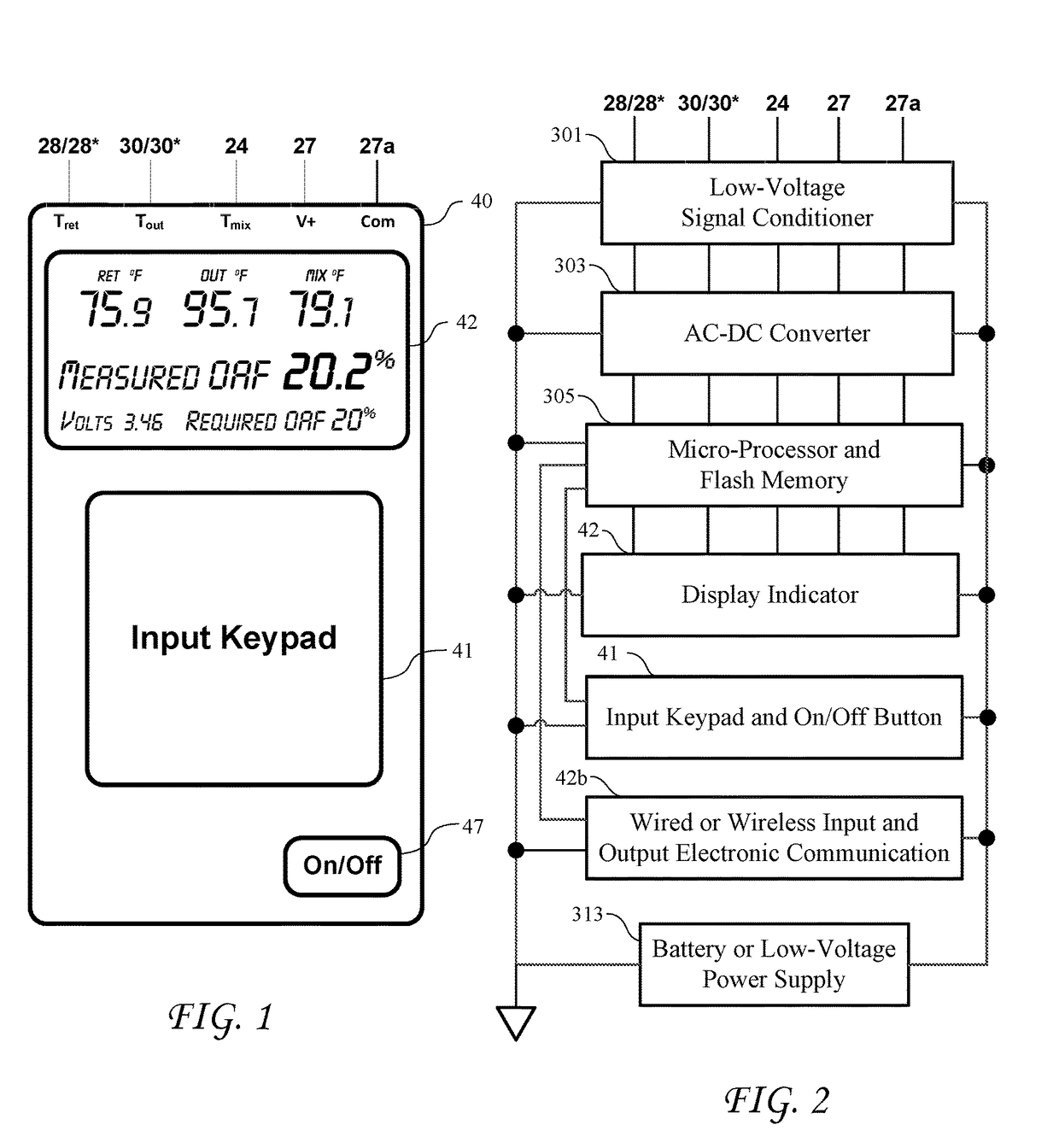
[0031]FIG. 1 shows a handheld measurement device 40 and FIG. 2 shows the electronic components of measurement devices 40, 40a or 40b (see FIGS. 3, 5 and 6). The measurement devices 40, 40a and 40b preferably include a low-voltage power supply or external power source 313, a signal conditioner ...


PUM


Abstract

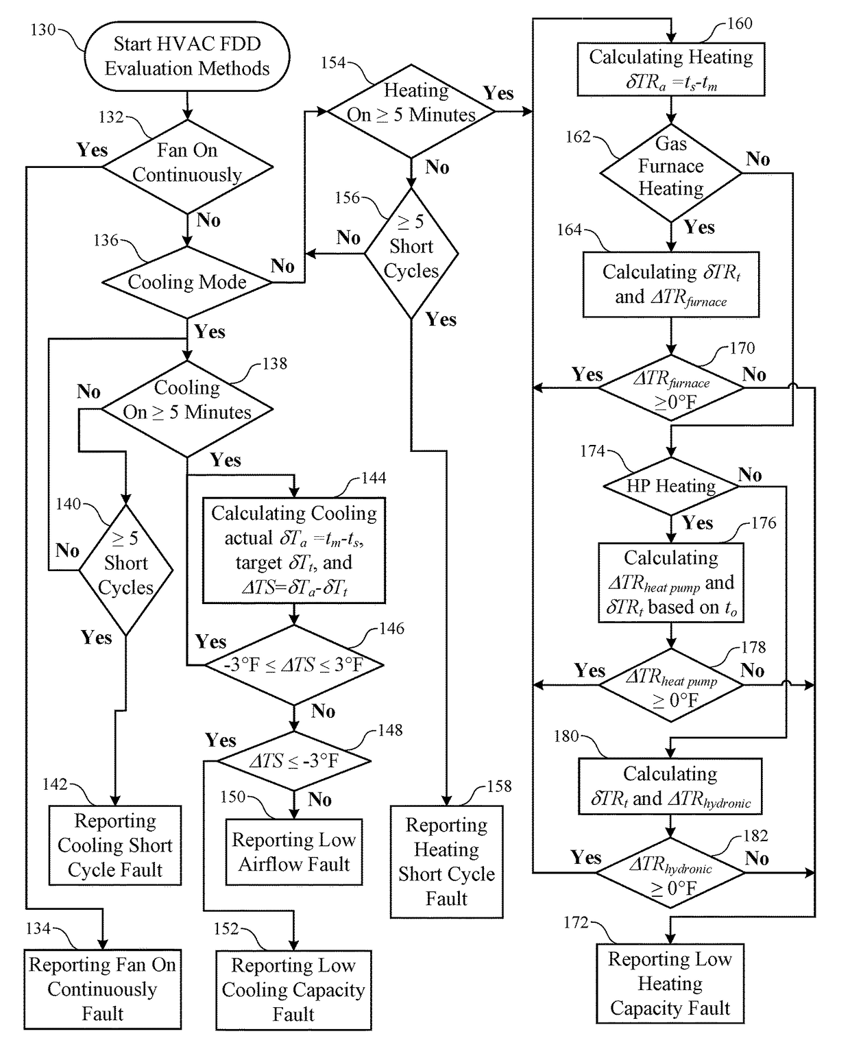
An apparatus and method for measuring or controlling the Outdoor Air Fraction (OAF) ratio through economizer or outdoor air dampers and cabinet to total system airflow and mixed-air humidity ratio and wetbulb temperature for HVAC equipment. An OAF exceeding the minimum regulatory requirements wastes energy and contributes to global warming. OAF is used to optimize economizer damper position either manually or automatically using an economizer Fault Detection Diagnostic controller and actuator to meet minimum outdoor airflow requirements. After the outdoor air damper position is optimized, the mixed-air humidity ratio and mixed-air wetbulb temperature are determined and used with the measured mixed-air drybulb and supply-air drybulb temperatures to evaluate evaporator airflow, cooling capacity, and heating capacity, and, if necessary, provide a visual or electronically-transmitted error code signal indicating maintenance requirements to check or correct economizer damper position, cabinet leakage, airflow, cooling or heating capacity, and / or other faults for the HVAC system.

Description

BACKGROUND OF THE INVENTION[0001]The present invention relates to Heating, Ventilating, and Air Conditioning (HVAC) systems and in particular to outdoor air introduced into buildings during HVAC operation through economizer outdoor air dampers or non-economizer outdoor air dampers.[0002]Buildings are required to provide a minimum flow of outdoor air into their HVAC systems per the American Society of Heating Refrigeration and Air-Conditioning Engineers (ASHRAE) Standard 61.1 (ANSI / ASHRAE 62.1-2010. Standard Ventilation for Acceptable Indoor Air Quality) and the California Energy Commission (CEC) Building Energy Efficiency Standards for Residential and Nonresidential Buildings (CEC-400-2012-004-CMF-REV2). When the outdoor airflow exceeds the minimum required airflow, the additional airflow may introduce unnecessary hot outdoor air when the HVAC system is cooling the building, or introduce unnecessary cold outdoor air when the HVAC system is heating the building. This unnecessary or u...

Claims


Application Information

Patent Timeline
Patent Type & Authority Applications(United States)
IPC IPC(8): F24F11/00
CPCF24F11/0001F24F11/0012F24F11/0015F24F11/006F24F2011/0061F24F2011/0013F24F2011/0016F24F2011/0052F24F2011/0056F24F2011/0002F24F2110/12F24F11/63F24F11/30F24F2110/20F24F2110/10F24F11/32F24F11/62F24F2140/40F24F2110/22F24F11/58F24F11/46F24F11/523F24F11/38F24F2140/00G06F16/24573
Inventor MOWRIS, ROBERT J.
Owner MOWRIS ROBERT J
Why Eureka
Eureka Blog
Learn More