Sample temperature control method

a temperature control and sample technology, applied in the direction of heat measurement, instruments, manufacturing tools, etc., can solve the problems of insufficient heat transfer between the sample stage and the sample placed thereon, and it takes a long time for the temperature of the wafer to reach the desired value, etc., to accurately estimate the sample temperature and stably control the sample temperature

Inactive Publication Date: 2009-12-17
HITACHI HIGH-TECH CORP
View PDF6 Cites 41 Cited by
  • Summary
  • Abstract
  • Description
  • Claims
  • Application Information

AI Technical Summary

Benefits of technology

[0007]The present invention has been worked out in view of the problems described above, and therefore an object of the invention is to provide a sample temperature control method capable of stably controlling a wafer temperature so as to attain a desired temperature by estimating a sample temperature accurately.
[0010]Since the present invention is configured as described above, it is possible to accurately estimate a sample temperature and stably control the sample temperature to a desired temperature.

Problems solved by technology

However, (1) heat transfer between the sample stage and a sample placed thereon is not sufficient.
Therefore, it takes a long time for wafer temperature to reach a desired value.

Method used


Image

  • Sample temperature control method
  • Sample temperature control method
  • Sample temperature control method

Examples


embodiment 1

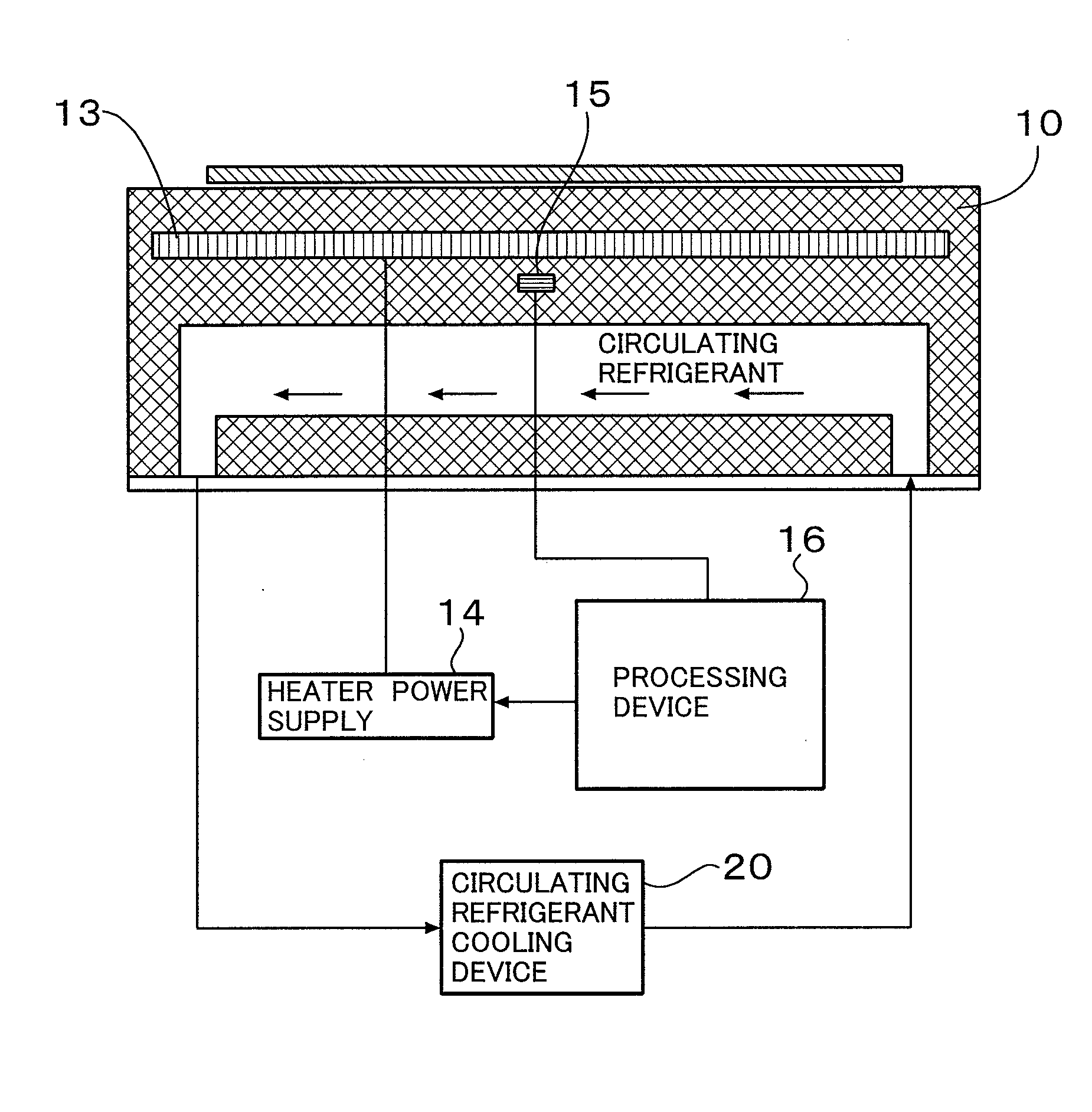
[0036]FIG. 6 is a diagram illustrating a microwave plasma etching apparatus having an automatic wafer temperature control function. In this apparatus, a microwave generated by a magnetron 5 is introduced into a decompression treatment chamber 1 via a wave guide 6 and a quartz window 7 to produce a plasma 8. At this time, a treatment gas introduced from a gas inlet 9 is dissociated by the plasma 8 and radicals and positive ions are produced. Also, a butterfly throttle valve 3 is provided between the decompression treatment chamber 1 and a pump and therefore it is possible to regulate a pressure in the decompression treatment chamber by regulating the degree of opening of the throttle valve 3.

[0037]Furthermore, a wafer 11 to be etched is placed on a sample stage 10 connected to a high frequency power supply. By applying an electric power to the sample stage from the high frequency power supply via a matching box, it is possible to generate a negative bias voltage in the wafer. The sam...

embodiment 2

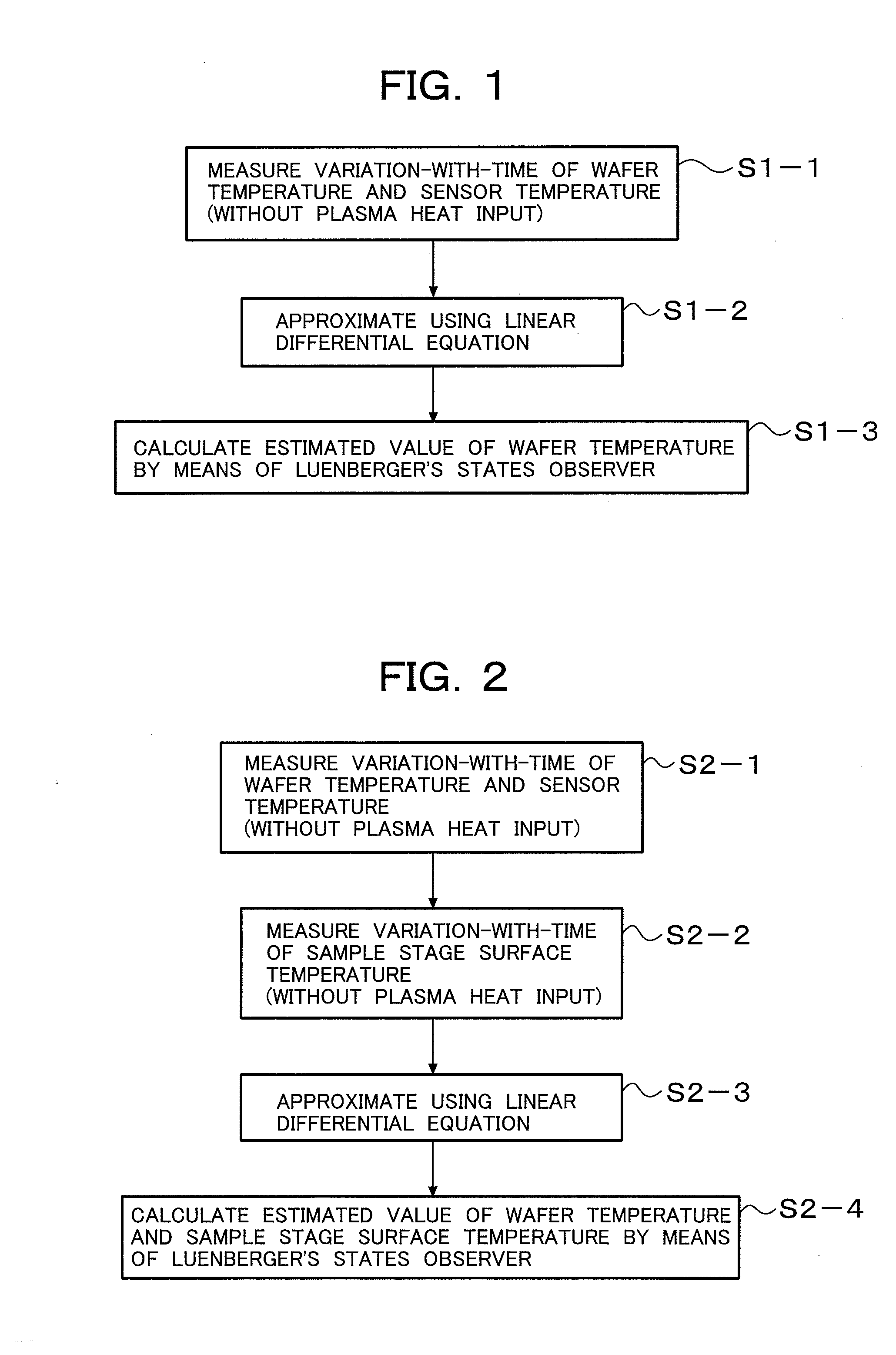
[0052]With reference to the etching apparatus shown in FIG. 6, the method of performing a second wafer temperature estimation control is described according to the procedure in FIG. 2.

[0053]First, at step S2-1, the variation-with-time of wafer temperature x1 and sensor temperature y1 of each of the center, middle, and edge regions are measured the same as at step S1-1 in the embodiment 1. At step S2-2, heater electric power u1 is incrementally increased in exactly the same time sequence as at step S2-1, and the variation of sample stage temperature x3 is measured with a radiation thermometer shown in FIG. 6. At step S2-3, the relation among heater electric power u1, wafer temperature x1, sensor temperature y1, and sample stage temperature x3, which were measured at steps S2-1 and S2-2, is approximated using equation (5). Specifically, the value of a constant matrix A11 to A33, B11 to B31 is determined using the method of least squares.

Equation5t[y1x2x3]=[A11A12A13A21A22A23A31A32A33]...


PUM

PropertyMeasurementUnit
pressureaaaaaaaaaa
temperatureaaaaaaaaaa

Abstract

A method of stably controlling the temperature of a sample placed on a sample stage to a desired temperature by estimating a sample temperature accurately, the sample stage including a refrigerant flow path to cool the sample stage, a heater to heat the sample stage, and a temperature sensor to measure the temperature of the sample stage. This method comprises the steps of: measuring in advance the variation-with-time of supply electric power to the heater, temperature of the sample, and temperature of the temperature sensor, without plasma processing; approximating the relation among the measured values using a simultaneous linear differential equation; estimating a sample temperature from the variation-with-time of sensor temperature y1, heater electric power u1, and plasma heat input by means of the Luenberger's states observer based on the simultaneous linear differential equation used for the approximation; and performing a feedback control of sample temperature using the estimated sample temperature.

Description

BACKGROUND OF THE INVENTION[0001]1. Field of the Invention[0002]The present invention relates to a sample temperature control method, and more specifically relates to a method of temperature control in a plasma processing apparatus.[0003]2. Description of the Related Art[0004]FIG. 18 is a diagram illustrating a conventional method of adjusting sample temperatures. As shown in FIG. 18, a sample is placed on a sample stage 10 cooled by a refrigerant. The sample stage has an embedded heater 13 and is configured to regulate an amount of heat by regulating the electric power to be supplied to the heater 13. Furthermore, the sample stage has an embedded temperature sensor 15 capable of measuring a temperature of the sample stage 10 (refer to Japanese Unexamined Patent Application Publication No. 2005-522051 and its corresponding U.S. Pat. No. 6,921,724).[0005]FIG. 19 is a diagram illustrating a conventional temperature control apparatus. As shown in drawing, the apparatus employs a feedba...

Claims


Application Information

Patent Timeline
Patent Type & Authority Applications(United States)
IPC IPC(8): G01K17/00
CPCG01K13/00H01L21/67248H01L21/67109
Inventor KOFUJI, NAOYUKITSUBONE, TSUNEHIKO
Owner HITACHI HIGH-TECH CORP
Why Eureka
Try Eureka