Manifold assembly

a manifold and assembly technology, applied in the field of manifold assemblies, can solve the problems of affecting the integrity or operation of the manifold, limiting or constraining the structural arrangement unable to inspect, service, repair or replace the components of the manifold assembly, etc., to achieve the effect of reducing dynamic loading

Active Publication Date: 2015-01-01
SPM OIL & GAS INC
View PDF22 Cites 63 Cited by
  • Summary
  • Abstract
  • Description
  • Claims
  • Application Information

AI Technical Summary

Benefits of technology

[0004]In a first aspect, there is provided a manifold assembly that includes a skid; a low pressure manifold connected to the skid, the low pressure manifold including one or more flow lines through which fluid is adapted to flow, and a plurality of ports connected to the one or more flow lines and via which respective portions of the fluid are adapted to flow to corresponding pumps in a plurality of pumps; a high pressure manifold connected to the skid, the high pressure manifold including a plurality of fittings, each of the respective portions of the fluid being adapted to flow through at least one of the fittings in the plurality of fittings after exiting the corresponding pump; and a plurality of vibration isolators to dampen dynamic loading, the plurality of vibration isolators being disposed between the fittings and the one or more flow lines.

Problems solved by technology

In some cases, the high and / or low pressure manifolds may vibrate or otherwise experience dynamic loading, which dynamic loading may ultimately affect the integrity, or operation, of the manifold(s).
In addition to, or instead of, issues related to dynamic loading, it is sometimes difficult to inspect, service or repair the manifold assembly, or to inspect, service, repair or replace components of the manifold assembly.
Still further, if the manifold assembly is mounted on a trailer, height restrictions may limit or constrain the structural arrangement of the manifold assembly.

Method used


Image

  • Manifold assembly
  • Manifold assembly
  • Manifold assembly

Examples


Embodiment Construction

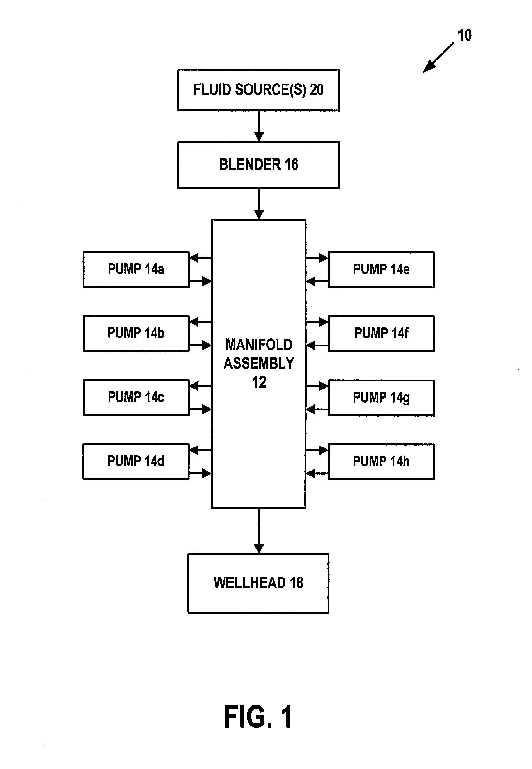
[0066]In an exemplary embodiment, as illustrated in FIG. 1, a system is generally referred to by the reference numeral 10 and includes a manifold assembly 12. Pumps 14a-14h, a blender 16, and a wellhead 18 are in fluid communication with the manifold assembly 12. One or more fluid sources 20 are in fluid communication with the blender 16. The wellhead 18 is the surface termination of a wellbore (not shown). In an exemplary embodiment, the one or more fluid sources 20 include one or more fluid storage tanks, other types of fluid sources, natural water features, or any combination thereof. In an exemplary embodiment, the system 10 is part of a hydraulic fracturing (or “frac”) system, which may be used to facilitate oil and gas exploration and production operations. The exemplary embodiments provided herein are not limited to a hydraulic fracturing system as the exemplary embodiments may be used with, or adapted to, a mud pump system, a well treatment system, other pumping systems, one...


PUM


Abstract

According to one aspect, a manifold assembly includes a skid, a low pressure manifold connected to the skid, and a high pressure manifold connected to the skid. In another aspect, the high pressure manifold has a modular configuration so that the high pressure manifold is disconnectable in whole or in part from the skid, and reconnectable in whole or in part to the skid. In yet another aspect, the high pressure manifold includes high pressure modules, all of which are in fluid communication with each other and each of which is adapted to be in fluid communication with at least one pump. In still yet another aspect, the low pressure manifold includes one or more flow lines, the high pressure manifold includes fittings, and the manifold assembly includes vibration isolators to dampen dynamic loading, the vibration isolators being disposed between the fittings and the one or more flow lines.

Description

CROSS-REFERENCE TO RELATED APPLICATION[0001]This application claims the benefit of the filing date of, and priority to, U.S. patent application No. 61 / 841,753, filed Jul. 1, 2013, the entire disclosure of which is hereby incorporated herein by reference.TECHNICAL FIELD[0002]This disclosure relates in general to manifold assemblies and, in particular, a manifold assembly that includes a low pressure manifold and a high pressure manifold.BACKGROUND OF THE DISCLOSURE[0003]A manifold assembly may include a low pressure manifold and a high pressure manifold. Such a manifold assembly may be used to hydraulically fracture (or “frac”) a subterranean formation by conveying pressurized fluid to a wellbore that extends within the subterranean formation, thereby facilitating oil and gas exploration and production operations. In some cases, the high and / or low pressure manifolds may vibrate or otherwise experience dynamic loading, which dynamic loading may ultimately affect the integrity, or ope...

Claims


Application Information

Patent Timeline
Patent Type & Authority Applications(United States)
IPC IPC(8): F16L41/02F16L3/08
CPCF16L3/08F16L41/02F16L55/035E21B43/26F16F7/14F16L41/03Y10T137/6966Y10T137/85938E21B43/2607
Inventor ARIZPE, RONTSUEI, LUNLONG, TIMOTHYHARDMAN, ADAMGREEN, MATTHEW
Owner SPM OIL & GAS INC
Why Eureka
Try Eureka