Propane vaporizer for fuel powered devices

a technology of propane vaporizer and fuel powered devices, which is applied in the field of vaporizers, can solve the problems of high price of pressure vessels and the danger of operation of them

Inactive Publication Date: 2004-06-29
NEUFELDT ALLEN A
View PDF5 Cites 4 Cited by
  • Summary
  • Abstract
  • Description
  • Claims
  • Application Information

AI Technical Summary

Problems solved by technology

Pressure vessels are expensive and they can be dangerous to operate.

Method used


Image

  • Propane vaporizer for fuel powered devices
  • Propane vaporizer for fuel powered devices
  • Propane vaporizer for fuel powered devices

Examples


Embodiment Construction

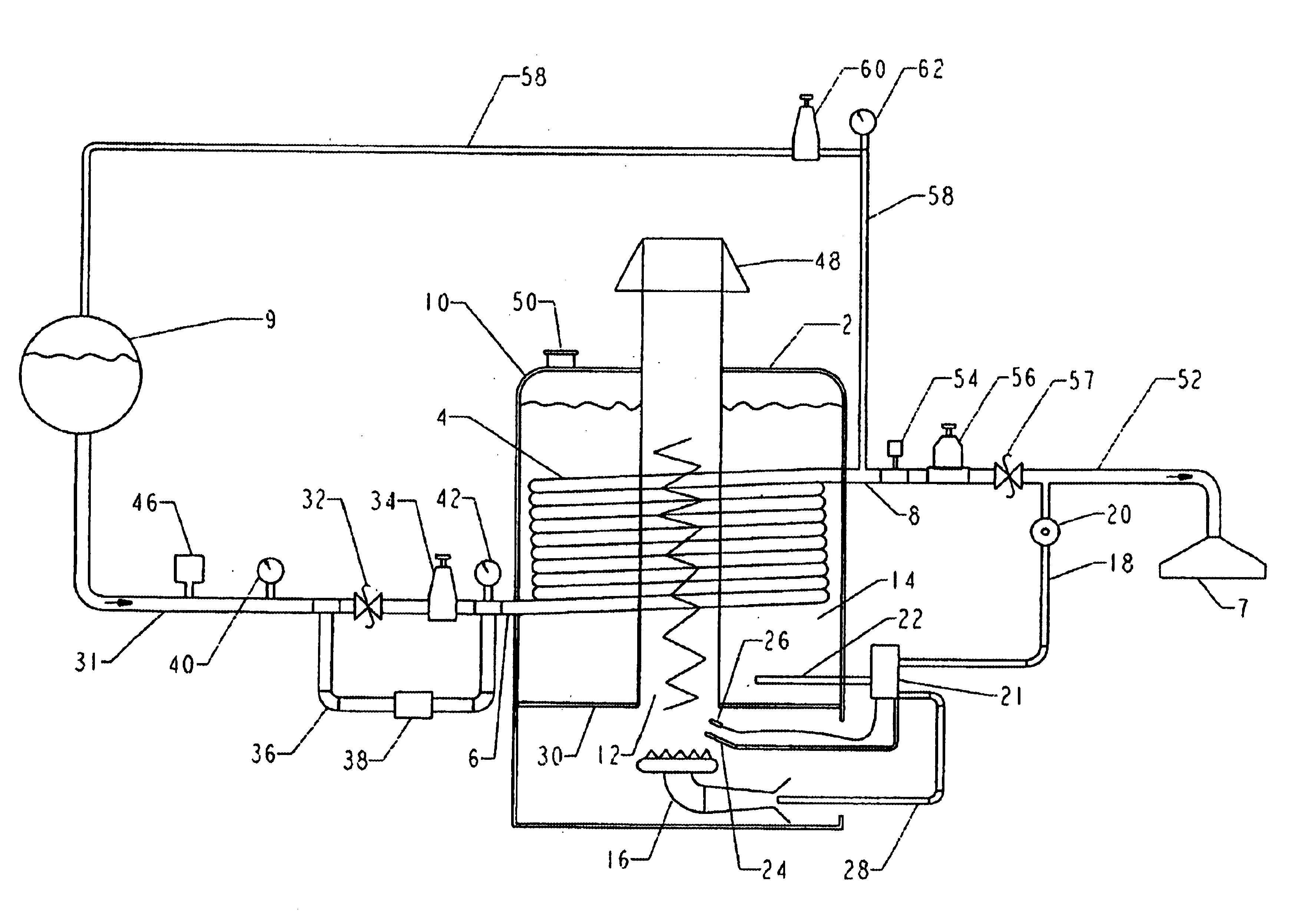
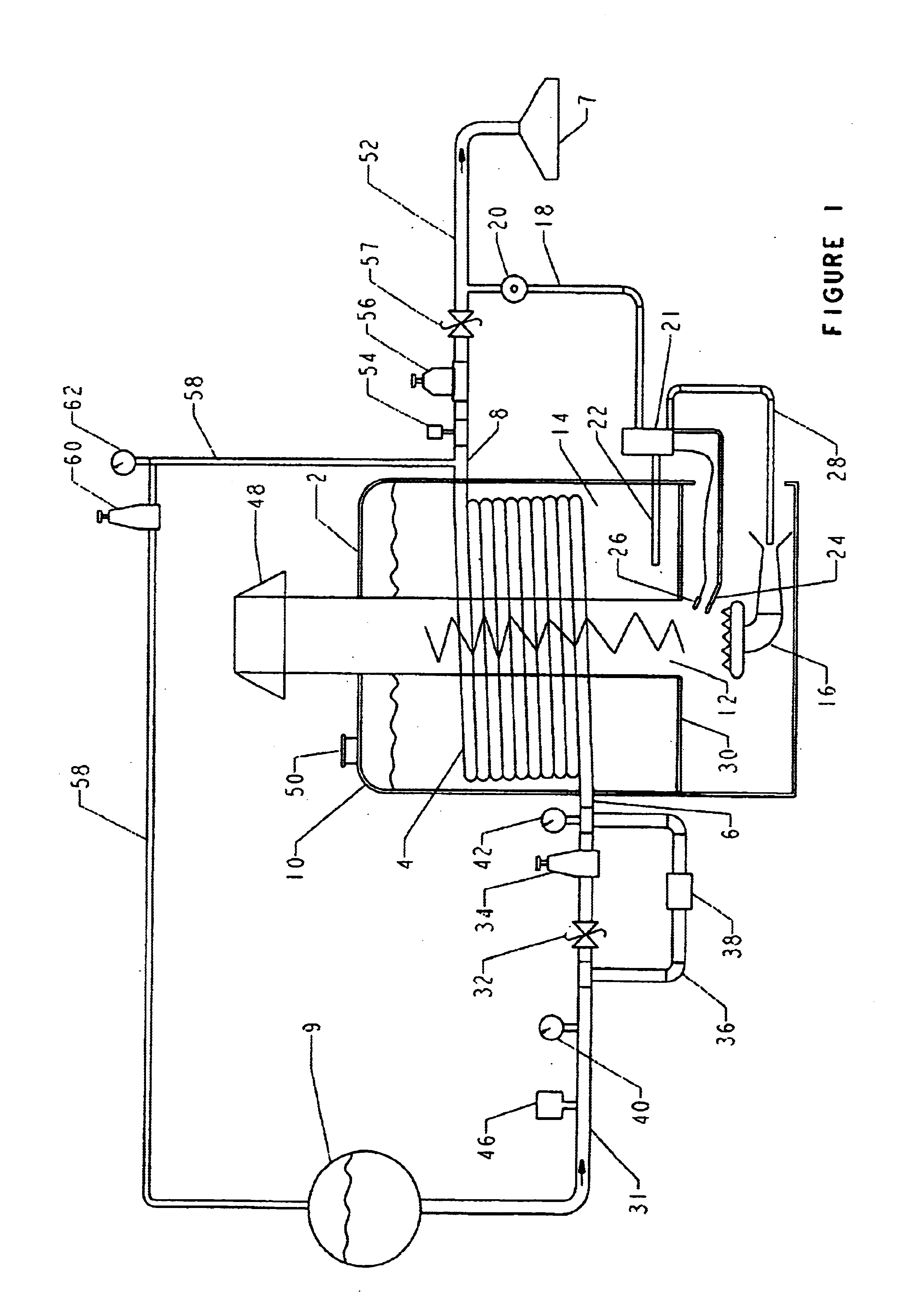
In FIG. 1, a vaporizer 2 has a coil 4 with an inlet 6 and an outlet 8. The outlet 8 is connected to a fuel powered device 7 and the inlet 6 is connected to a supply of liquid petroleum gas 9. The coil is located within a housing 10, the housing having a centrally located opening or flue 12 extending therethrough. The housing 10 contains a bath 14 and the liquid of the bath is preferably water. There is sufficient water forming the bath 14 to completely immerse the coil 4. A burner 16 is connected to a secondary line 18 extending from the outlet 8. The secondary line 18 has a low pressure regulator 20 to reduce the pressure of vaporized fuel through the secondary line 18 to a temperature controller 21. The controller 21 has a temperature probe 22 extending through a wall of the housing 10 into the bath 14. The temperature controller 21 controls the flow of gas to a pilot light 24 having a thermocouple 26. The temperature controller 21 is connected to a burner line 28, which in turn i...


PUM


Abstract

A vaporizer is connected to a liquid propane supply. The vaporizer contains a helical coil immersed in a bath. A pressure regulator at an inlet to the coil reduces the pressure and vaporizes part of the propane. A burner connected to the outlet of the vaporizer is used to heat the bath. Part of the vapor is returned to the supply to pressurize the supply. The main part of the vapor from the outlet is used to power a fuel powered device.

Description

1. Field of the InventionThis invention relates to a vaporizer to vaporize liquid petroleum gas. More particularly, this invention relates to a vaporizer that is used outdoors to operate fuel powered devices using liquid propane, butane, isobutane and the like.2. Description of the Prior ArtVaporizers for liquid propane and other liquid petroleum gases exist. Most vaporizers use pressure vessels. Liquid propane expands as it cools and pressure is reduced. The pressure vessel is usually heated with direct flame to vaporize the propane. Over time, a residue accumulates in the pressure tank. Usually, the pressure vessel has a temperature sensing device to control the temperature of the liquid and a float to prevent liquid from exiting through the outlet of the vaporizer. Pressure vessels are expensive and they can be dangerous to operate.Propane vaporizers used in motor vehicles for carburetion are quite small. Water from the cooling system of the motor vehicle is used to vaporize the ...

Claims


Application Information

Patent Timeline
Patent Type & Authority Patents(United States)
IPC IPC(8): F23K5/20F23K5/02F23D11/36F23D11/44
CPCF23D11/445F23K5/20
Inventor NEUFELDT, ALLEN A.
Owner NEUFELDT ALLEN A
Why Eureka
Try Eureka