Energy-saving electrical adaptor

a technology of electrical adaptors and adapters, applied in emergency protective devices, lighting devices, electric lighting sources, etc., can solve the problems of increasing strain on standard power grids, users often neglecting to take such steps, and periods of non-us

Inactive Publication Date: 2008-07-10
LITWACK MARK W
View PDF6 Cites 46 Cited by
  • Summary
  • Abstract
  • Description
  • Claims
  • Application Information

AI Technical Summary

Benefits of technology

[0005]According to one embodiment of the present invention, a power conservation connector is used containing a power inlet for providing power to the power conservation apparatus and to an external appliance, a power outlet operable to be connected to the appliance, a relay coupling the power inlet and the power outlet, a current sensor operable to measure a current flow from the power outlet to the appliance, a threshold detector operable to receive an input in accordance with the current flow and operable to determine if the appliance is in a state of non-use, and a timer having a set-point; wherein the timer is activated upon the appliance entering the state of non-use and wherein the relay is opened upon the timer reaching the set-point, so as to prevent both the power conservation apparatus and the appliance from drawing power from the power inlet.

Problems solved by technology

Electrical appliances that are typically found in homes and business consume electricity even when the appliance is not in use, and many consume electricity even after the appliance appears to have been turned off.
An increasing strain has also been placed on standard power grids due to the proliferation of appliances that require a continuous stand-by power.
This is particularly a problem when appliances enter prolonged periods of non-use.
Users will often neglect to take such steps.

Method used


Image

  • Energy-saving electrical adaptor
  • Energy-saving electrical adaptor
  • Energy-saving electrical adaptor

Examples


Embodiment Construction

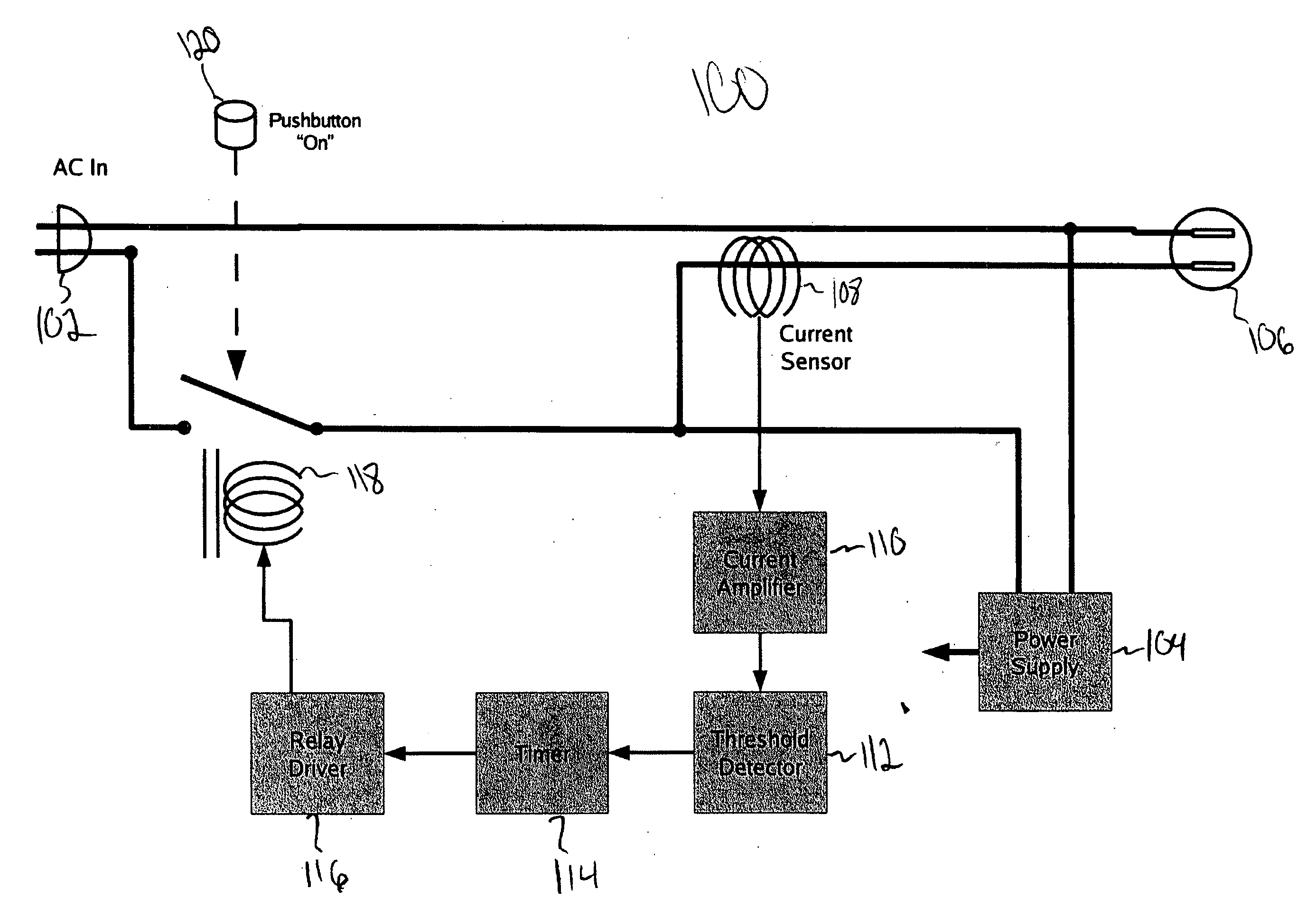
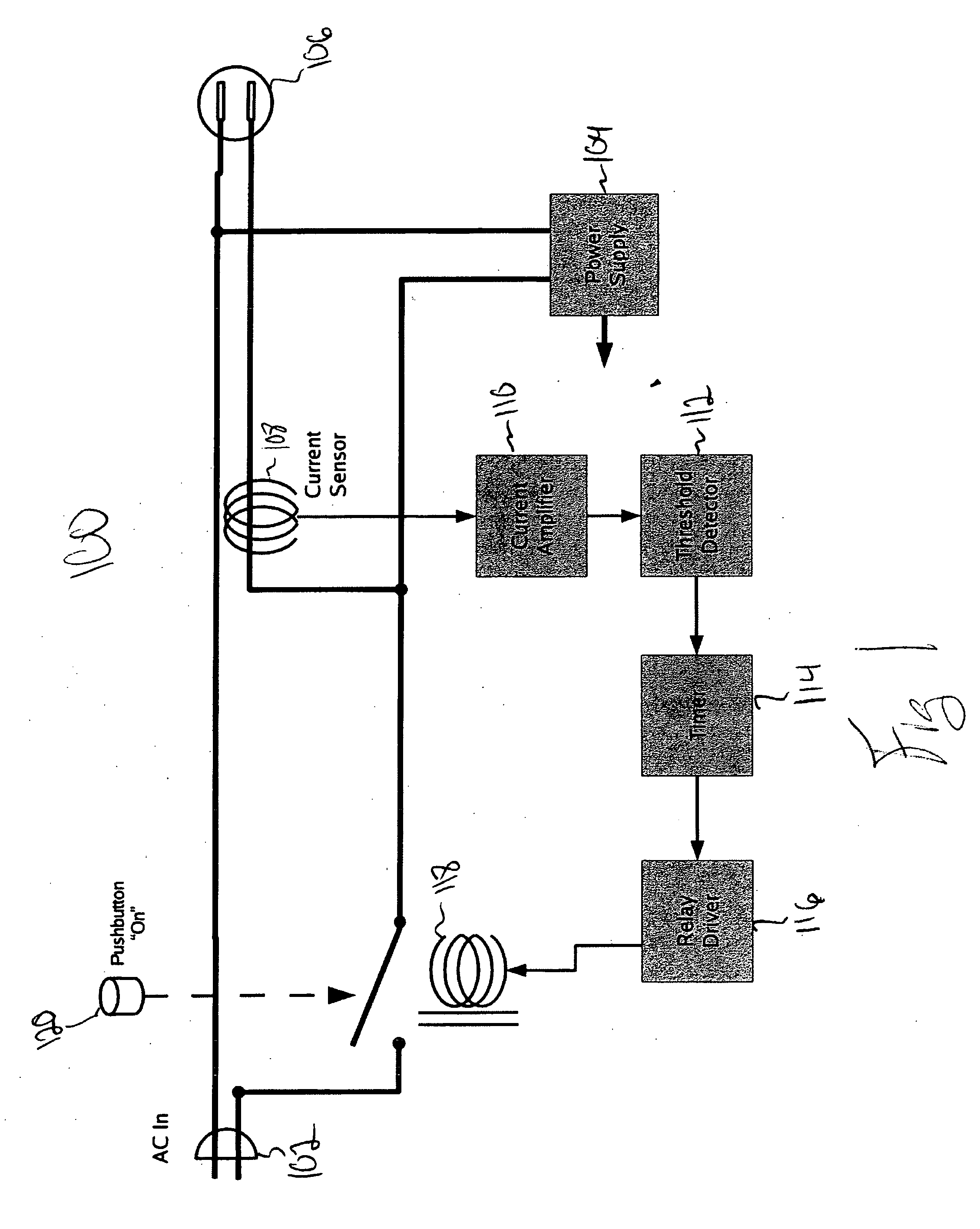
[0019]FIG. 1 illustrates a power connector 100 in accordance with one embodiment of the invention. In this embodiment, a relay is used in conjunction with a current sensor and a timer in order to completely deactivate an electrical device after a period of non-use, so that no power is drawn by either the electrical device or the power connector 100. As shown in FIG. 1, the power connector 100 includes an AC input 102 that is coupled to a power supply 104 and an AC outlet 106. A current sensor 108 is coupled to the AC outlet 106 so as to be operable to determine the current being drawn from the AC outlet 106. Connected to the current sensor 108 is a current amplifier 110, which is in turn connected to a threshold detector 112. The threshold detector 112 is coupled to a timer 114 so as to determine the period of time for which the current sensor 108 has detected a current that is below a predetermined threshold. The timer 114 is coupled to a relay driver 116, which is in turn coupled ...


PUM


Abstract

A power conservation apparatus having a power inlet for providing power to the power conservation apparatus and an external appliance, a power outlet operable to be connected to the appliance, a relay coupling the power inlet and the power outlet, a current sensor operable to measure a current flow from the power outlet to the appliance, a threshold detector operable to receive an input in accordance with the current flow and operable to determine if the appliance is in a state of non-use, and a timer having a set-point; wherein the timer is activated upon the appliance entering the state of non-use and wherein the relay is opened upon the timer reaching the set-point, so as to prevent the power conservation apparatus and the appliance from drawing power from the power inlet. When in the “off” state, the AC power consumed by the apparatus and coupled appliances is zero.

Description

BACKGROUND OF THE INVENTION[0001]This invention relates to a power conservation device to be used in connection with a variety of electrical appliances.[0002]Electrical appliances that are typically found in homes and business consume electricity even when the appliance is not in use, and many consume electricity even after the appliance appears to have been turned off. This is frequently referred to as the appliance's “stand-by” power, which is used to keep certain circuitry active and ready to respond to a potential user. Typically, the electricity drawn by appliances during the stand-by mode is only a small fraction of the electricity that is drawn when the appliance is in use. However, as many homes and businesses are switching to alternative energy sources, such as solar power, the need for lower levels of power consumption has become more important. An increasing strain has also been placed on standard power grids due to the proliferation of appliances that require a continuou...

Claims


Application Information

Patent Timeline
Patent Type & Authority Applications(United States)
IPC IPC(8): H02B1/24
CPCH05B37/0281Y02B20/42Y02B20/40H05B47/16
Inventor LITWACK, MARK W.
Owner LITWACK MARK W
Why Eureka
Try Eureka