
Power cycle test method for testing an electronic equipment

a technology of electronic equipment and power cycle, which is applied in the direction of measuring devices, testing dielectric strength, instruments, etc., can solve the problems of not ensuring the efficiency and correctness of each power cycle test, and requiring a lot of manual work during each power cycle tes

Inactive Publication Date: 2008-07-10
HONG FU JIN PRECISION IND (SHENZHEN) CO LTD +1
View PDF4 Cites 18 Cited by
  • Summary
  • Abstract
  • Description
  • Claims
  • Application Information

AI Technical Summary

Benefits of technology

The power cycle test method described in this patent allows for the testing of electronic equipment using a host computer, single chip processor, relay, and power supply. The method includes steps to define the total test count, reset the current test count, update the current test count, check if the equipment passes an AC test, power off the equipment if it passes the AC test, check if the equipment passes a DC test, power off the equipment if it passes the DC test, check if the equipment passes a reboot test, power off the equipment if it passes the reboot test, determine if the current test count is equal to the total test count, and display a result message if the current test count is equal to the total test count. The technical effect of this method is to provide a reliable and efficient way to test electronic equipment for proper functionality and performance.

Problems solved by technology

The technical problem addressed in this patent is the lack of efficient and accurate testing methods for electronic equipment, particularly with regards to power cycle tests which require both AC and DC stages. Current practices involve individual tests requiring significant amounts of manual labor, resulting in low efficiencies and potential errors. A solution is necessary to automate these tests and ensure their accuracy and effectiveness.

Method used


Image

  • Power cycle test method for testing an electronic equipment
  • Power cycle test method for testing an electronic equipment
  • Power cycle test method for testing an electronic equipment

Examples


Embodiment Construction

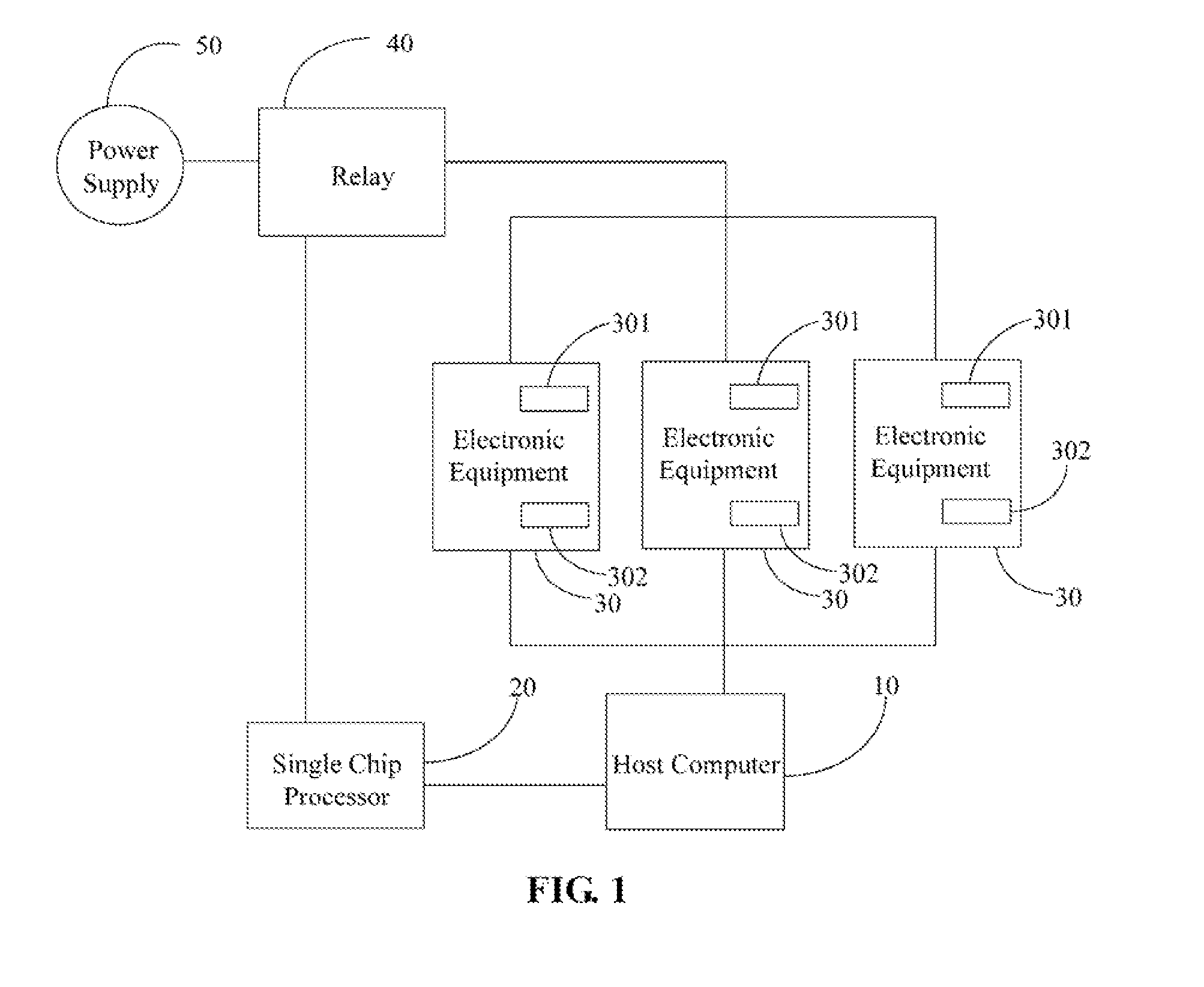
[0013]FIG. 1 is a schematic diagram of a hardware configuration of a power cycle test method for testing one or more electronic equipments in accordance with a preferred embodiment. The hardware configuration includes a host computer 10, a single chip processor 20, one or more electronic equipments 30 (only three shown in FIG. 1), a relay 40, and a power supply 50. The host computer 10 is connected with the single chip processor 20, and connected with the electronic equipments 30. The relay 40 is connected with the single chip processor 20. The power supply 50 is connected with the electronic equipments 30 through the relay 40. Each electronic equipment 30 has a power switch 301, and a reboot switch 302. The electronic equipments 30 are selected from the group consisting of a personal computer (PC), a notebook computer, a server, and a television.

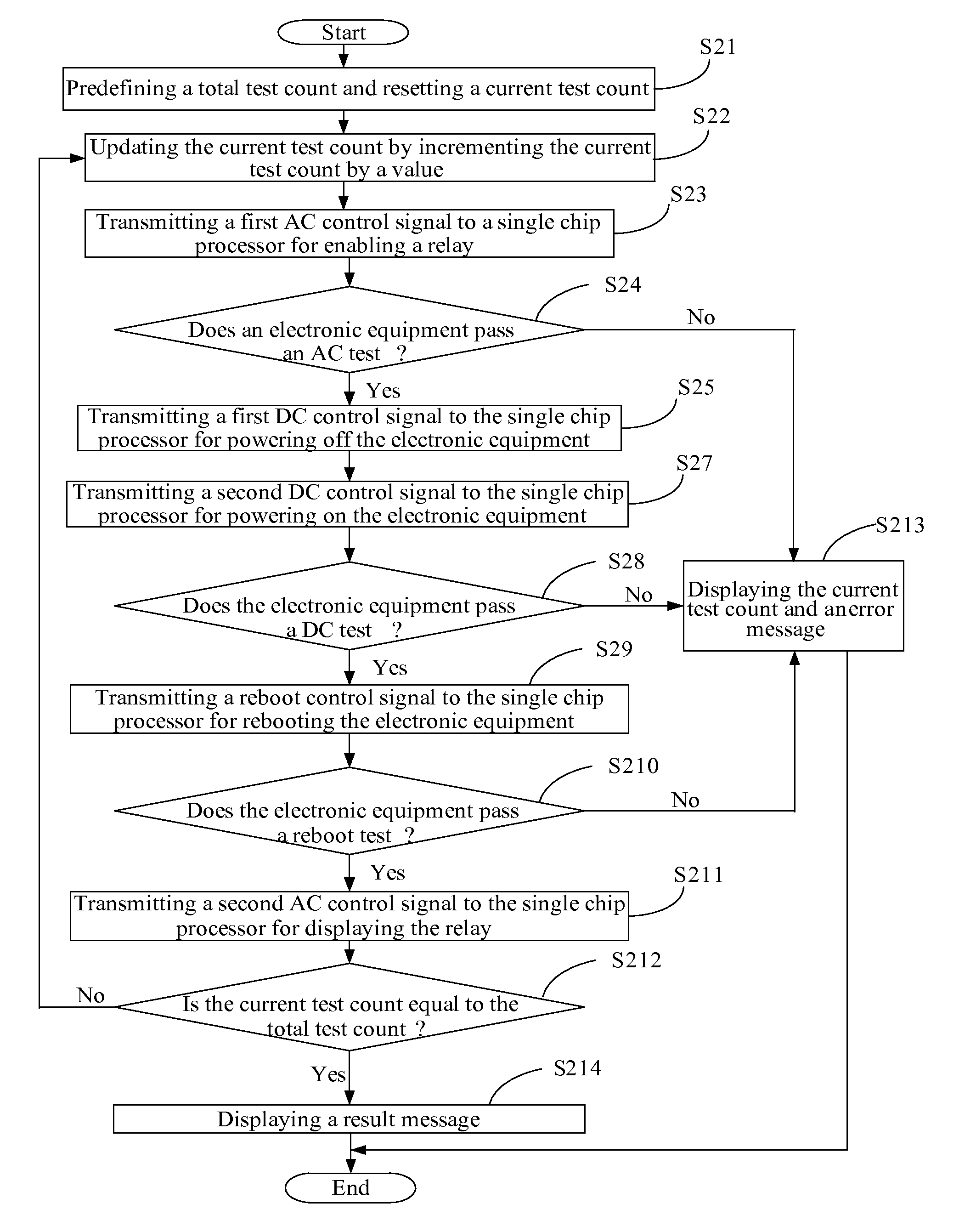
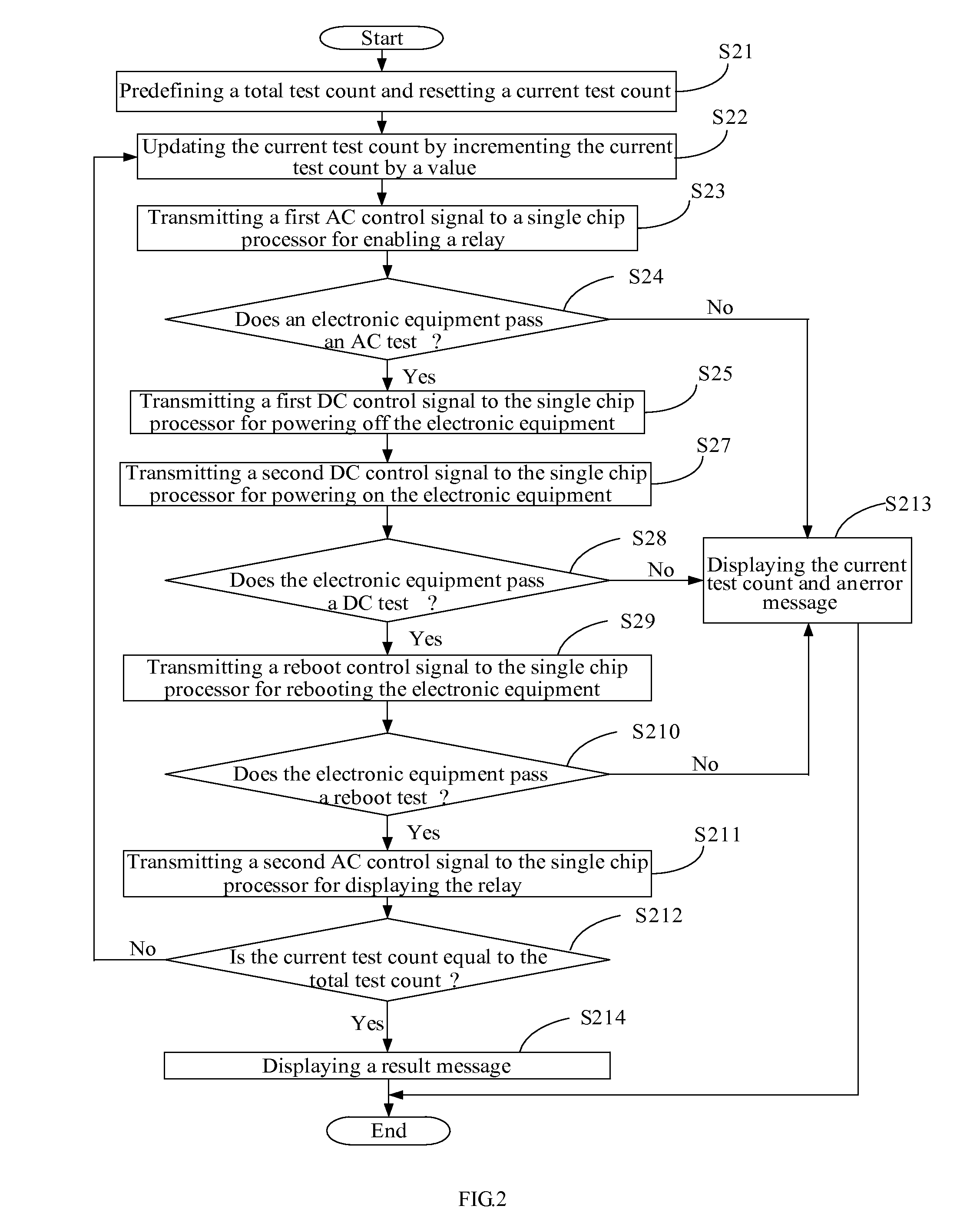
[0014]The host computer 10 is configured (structured and arranged) for performing power cycle tests on the electronic equipments 30 by emp...


PUM


Abstract

A power cycle test method for testing an electronic equipment (30) includes: configuring a total test count and a current test count; updating the current test count by incrementing the current test count by a value; utilizing a corresponding AC control signal, a corresponding DC control signal, and a reboot control signal to control the electronic equipment in sequence; checking whether the electronic equipment is in a workable condition when the electronic equipment is respectively controlled under said control signals; repeating said updating step, said utilizing step and said checking step until the current test count is equal to the total test count; and generating a result message if the current test count is equal to the total test count. A related system is also disclosed.

Description


Claims


Application Information

Patent Timeline
Owner HONG FU JIN PRECISION IND (SHENZHEN) CO LTD
Learn More