Focus adjustment device, imaging device and focus adjustment method

Inactive Publication Date: 2008-07-10
ELMO CO LTD
View PDF8 Cites 14 Cited by
  • Summary
  • Abstract
  • Description
  • Claims
  • Application Information

AI Technical Summary

Benefits of technology

[0009]By taking the problem accompanied with the mechanical backlash in the lens unit in

Problems solved by technology

In the lens unit, a backlash of the joint between the lead screw and the lens frame may lead to a variation in moving distance of the lens according to the moving direction of the lens.
Th

Method used


Image

  • Focus adjustment device, imaging device and focus adjustment method
  • Focus adjustment device, imaging device and focus adjustment method
  • Focus adjustment device, imaging device and focus adjustment method

Examples


Embodiment Construction

[0026]Some modes of carrying out the invention are described below in the following sequence with reference to the accompanied drawings:

[0027]A. Structure of Video Camera

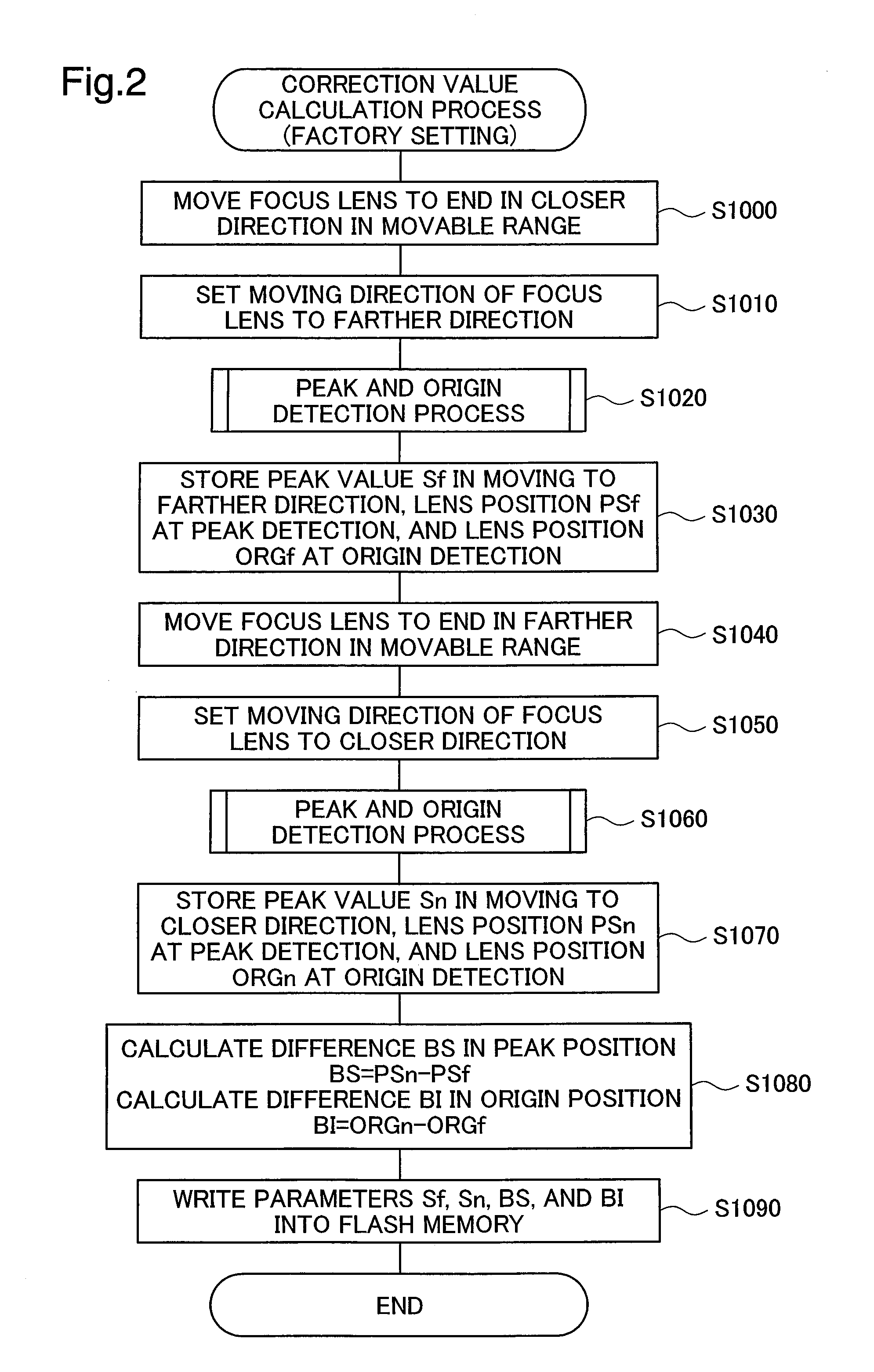
[0028]B. Correction Value Calculation Process for Factory Setting

[0029]C. Power-On Initialization Process

[0030]D. Auto Focusing Process[0031](D-1) Hill-Climbing Process[0032](D-2) Predictive Focus Value Estimation Process[0033](D-3) Focus Value Comparison Process

[0034]E. Other Aspects

A. Structure of Video Camera

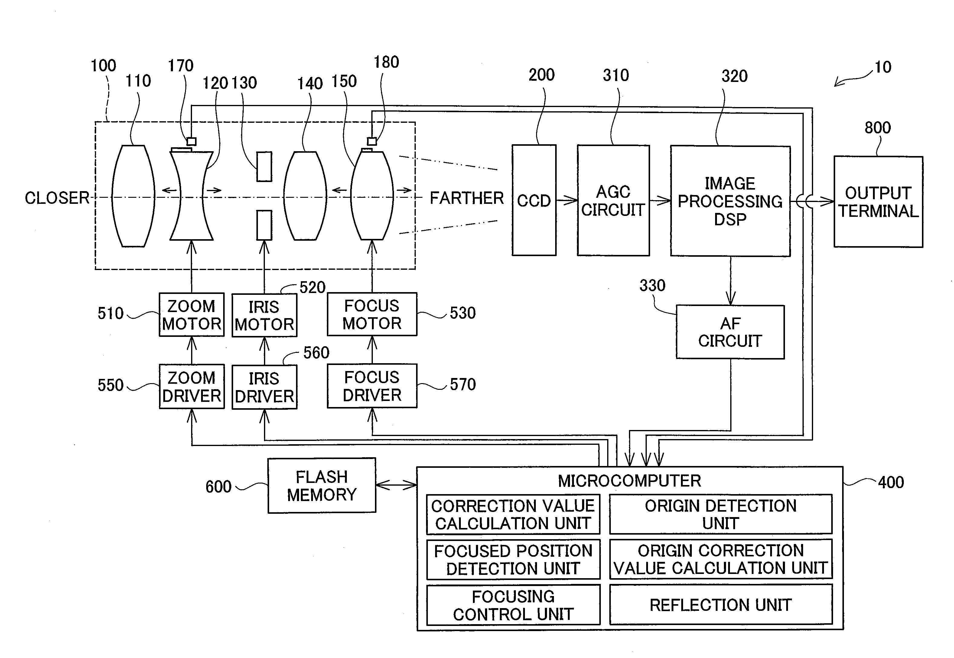
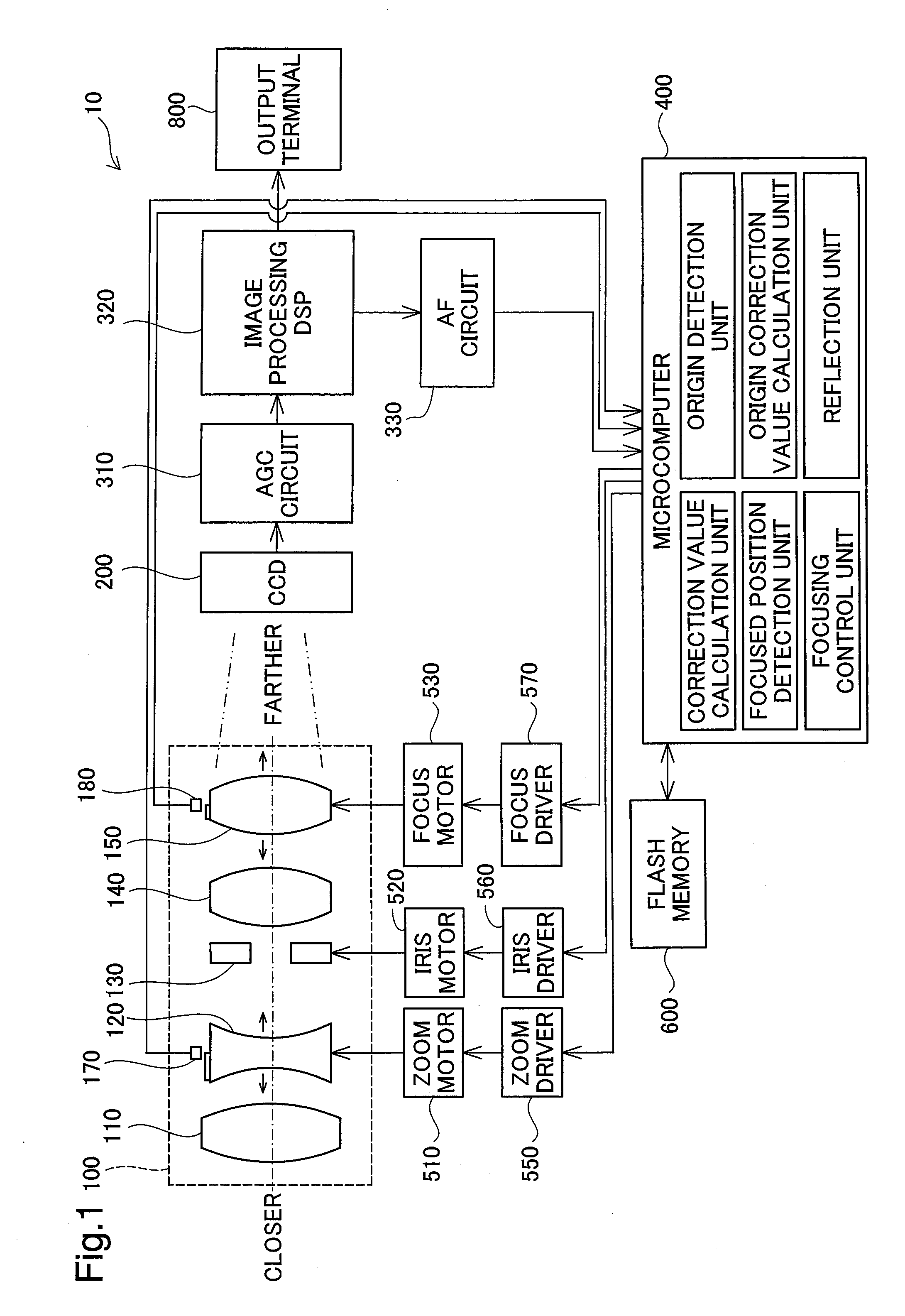
[0035]FIG. 1 shows the schematic structure of a video camera 10 in one embodiment of the invention. As illustrated, the video camera 10 of the embodiment includes a lens unit 100, a CCD 200, an AGC circuit 310, an image processing DSP (digital signal processor) 320, an AF circuit 330, a microcomputer 400, and a flash memory 600.

[0036]The lens unit 100 includes a first lens 110, a zoom lens 120, an iris mechanism 130, a third lens 140, and a focus lens 150, which are provided in this sequence from the subject ...


PUM


Abstract

A video camera constructed according to one aspect of the focus adjustment device moves a focus lens forward and backward and detects peak values of an AF evaluation value of the focus lens in the forward moving direction and in the backward moving direction. The video camera calculates a correction value based on a difference between the peak value of the evaluation value detected in the forward motion of the lens and the peak value of the evaluation value detected in the backward motion of the lens. The video camera corrects the AF evaluation value with the calculated correction value and detects a focused position of the lens based on the corrected AF evaluation value in moving the lens.

Description

CLAIM OF PRIORITY[0001]The present application claims the priority based on Japanese Patent Applications No. 2007-457 filed on Jan. 5, 2007, the disclosures of which are hereby incorporated by reference in its entirety.BACKGROUND[0002]1. Technical Field[0003]The present invention relates to a technology for automatically adjusting the focus of a lens.[0004]2. Related Art[0005]Latest still cameras and video cameras generally have the auto focusing function. One proposed technology of auto focusing control moves a focus lens in a lens unit to maximize an evaluation value calculated from a high frequency component of a luminance value of a captured image as shown in FIG. 12 (see, for example, Japanese Patent Laid-Open No. H07-87377 and No. H01-125065).[0006]A moving mechanism of moving the lens in the lens unit generally has a stepping motor equipped with a lead screw, a lens frame for supporting the lens, and a guide bar for guiding the motion of the lens frame in the direction of an ...

Claims


Application Information

Patent Timeline
IPC IPC(8): H04N5/232
CPCH04N5/23212H04N23/673
Inventor TOGUCHI, MASAAKI
Owner ELMO CO LTD
Why Eureka
Try Eureka