Active Vertebral Prosthetic Device

a prosthetic device and vertebral technology, applied in the field of active vertebral prosthetic devices, can solve the problems of inconvenient and expensive surgery, inconvenient operation, and inability to perform another surgery,

Inactive Publication Date: 2008-07-10
WARSAW ORTHOPEDIC INC
View PDF21 Cites 25 Cited by
  • Summary
  • Abstract
  • Description
  • Claims
  • Application Information

AI Technical Summary

Problems solved by technology

However, after implantation, there may be an occasional need to adjust the spinal disc.
For example, it is possible that the disc may not have been properly located by the operating physician.
In such instances, it is often not desirable to perform another surgery to correct the position of the disc.
Inserting the spinal disc can be an invasive and intensive procedure.
Further, because scar tissue may grow about the surgical site, any required second treatment can be more difficult, and may introduce additional distress to the patient.
In addition, due to either disc design or placement, the disc may not provide support that properly mimics a natural disc.
For example, fusion discs eliminate movement at the spinal joint, while articulating discs may not match the movement that occurs at a natural disc.

Method used


Image

  • Active Vertebral Prosthetic Device
  • Active Vertebral Prosthetic Device
  • Active Vertebral Prosthetic Device

Examples


Embodiment Construction

[0020]The present invention relates generally to vertebral reconstructive devices and, more particularly, to an intervertebral prosthetic device for implantation. For the purposes of promoting an understanding of the principles of the invention, reference will now be made to embodiments or examples illustrated in the drawings and specific language will be used to describe the same. It will nevertheless be understood that no limitation of the scope of the invention is thereby intended. Any alterations and further modifications in the described embodiments, and any further applications of the principles of the invention as described herein are contemplated as would normally occur to one skilled in the art to which the invention relates.

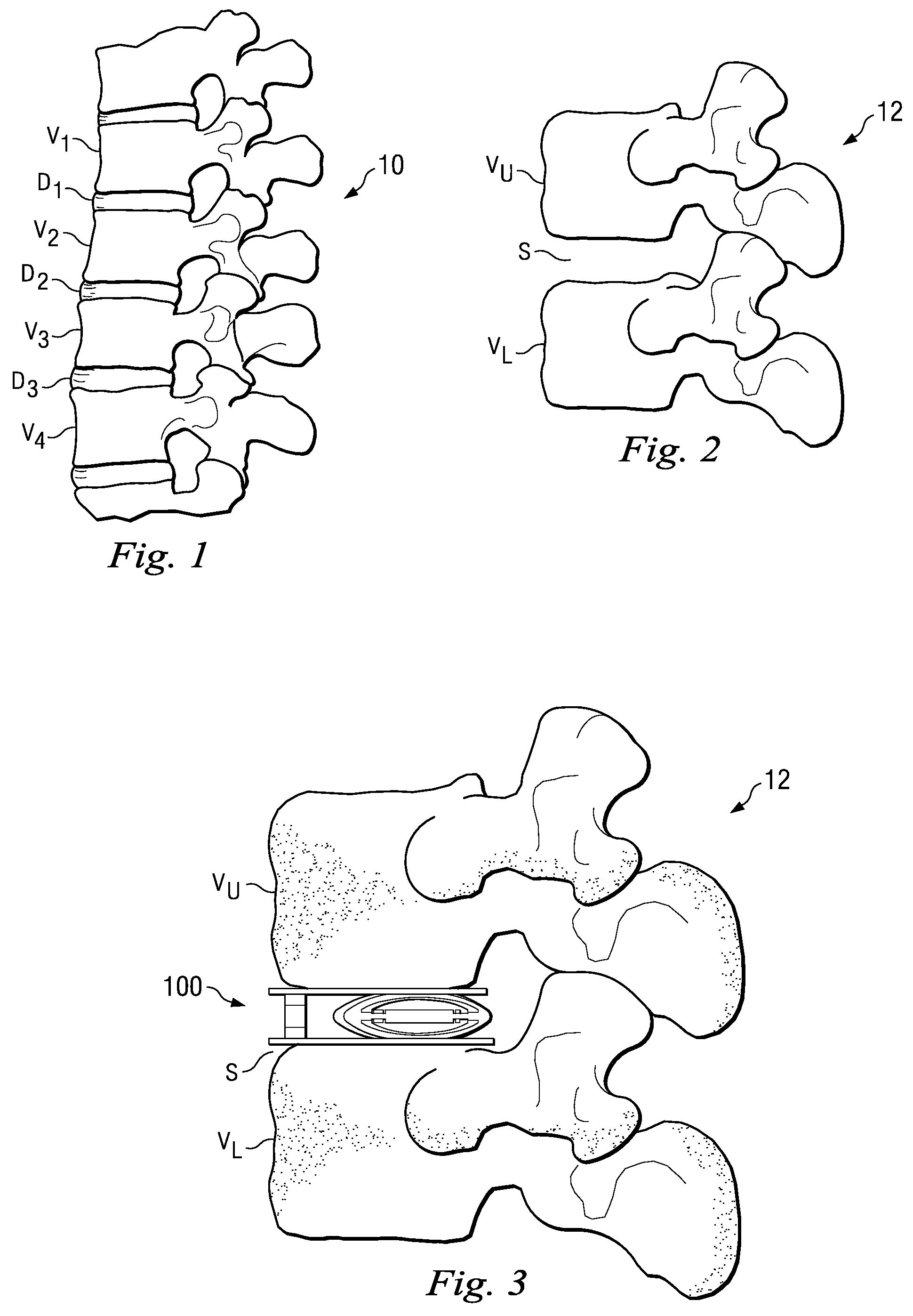
[0021]FIG. 1 shows a lateral view of a portion of a spinal column 10, illustrating a group of adjacent upper and lower vertebrae V1, V2, V3, V4 separated by natural intervertebral discs D1, D2, D3. The illustration of four vertebrae is only intended as ...


PUM

PropertyMeasurementUnit
angleaaaaaaaaaa
angleaaaaaaaaaa
distanceaaaaaaaaaa

Abstract

An active vertebral prosthetic device system may include an actuatable displacement element having an upper side and a lower side. The actuatable displacement element may be configured for placement between an upper vertebral body and a lower vertebral body and may be configured to alter the overall distance between the upper and the lower vertebral bodies in situ. A controller may be operable to post-surgically actuate the actuatable displacement element. In some aspects, the displacement element maybe a piezoelectric motor, an electroactive polymer, an ionic polymer metal composite, and an actuator.

Description

[0001]This application is related to co-pending U.S. patent application Ser. No. ______, titled Non-Rigid Intervertebral Spacers, having the same filing date as the present application, (Attorney Docket No. P26223 / 31132.626), incorporated herein in its entirety by referenceBACKGROUND[0002]Disc arthroplasty is one way of treating injured, degraded, or diseased spinal discs. Some disc arthroplasty treatments include replacing injured discs of the joint with either a fused or a motion-preserving spinal disc that replaces the injured disc at the spinal joint. However, after implantation, there may be an occasional need to adjust the spinal disc. For example, it is possible that the disc may not have been properly located by the operating physician. It is also possible that post-operative movement may occur prior to fusion or bonding with the associated vertebrae.[0003]In such instances, it is often not desirable to perform another surgery to correct the position of the disc. Inserting t...

Claims


Application Information

Patent Timeline
Patent Type & Authority Applications(United States)
IPC IPC(8): A61F2/44
CPCA61F2/442A61F2310/00796A61F2002/30131A61F2002/30538A61F2002/3055A61F2002/30571A61F2002/30663A61F2002/30884A61F2002/30906A61F2002/30925A61F2002/443A61F2002/701A61F2002/707A61F2230/0013A61F2250/0006A61F2310/00017A61F2310/00023A61F2310/00029A61F2310/00239A61F2002/30087
Inventor PROTOPSALTIS, DIMITRI K.
Owner WARSAW ORTHOPEDIC INC
Why Eureka
Try Eureka