Packaging process capable of improving stability of ionic polymer metal composite (IPMC) driver

A packaging process and driver technology, applied in the manufacture/assembly of piezoelectric/electrostrictive devices, etc., can solve the problems of reverse relaxation, difficulty in accurately controlling internal water content, performance attenuation, etc., and reduce the curing time Effect

Inactive Publication Date: 2013-09-04
XI AN JIAOTONG UNIV
View PDF4 Cites 6 Cited by
  • Summary
  • Abstract
  • Description
  • Claims
  • Application Information

AI Technical Summary

Problems solved by technology

[0003] When IPMC is directly used as a driver, there are two obvious defects: on the one hand, the IPMC driver deforms rapidly under the action of DC voltage, and at the same time has reverse relaxation phenomenon; on the other hand, the IPMC driver itself contains certain moisture and cann

Method used


Image

  • Packaging process capable of improving stability of ionic polymer metal composite (IPMC) driver
  • Packaging process capable of improving stability of ionic polymer metal composite (IPMC) driver
  • Packaging process capable of improving stability of ionic polymer metal composite (IPMC) driver

Examples


Embodiment 1

[0026] Parylene Coated IPMC Driver Package

[0027] (1) Make the IPMC driver and connect the lead electrodes

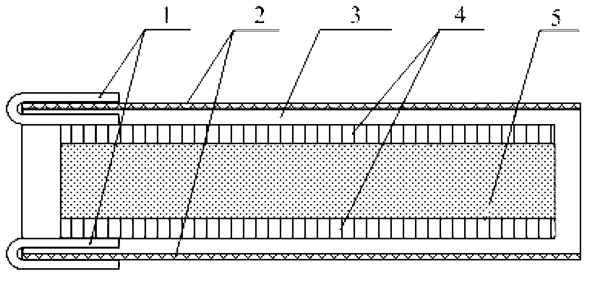
[0028] Connect upper and lower surface electrodes 4 respectively at the IPMC core layer ionic membrane 5 to form an IPMC driver; make two initial extraction electrodes 1, one of which is bonded to the edge of the upper surface electrode at one end of the IPMC driver, and the other is bonded to the end of the IPMC driver. Edge bonding of surface electrodes ( figure 1 ), and then put the IPMC driver with the initial lead-out electrode 1 into the bracket above the solution filled with saturated NaCl at the bottom of the airtight container to exchange and balance for 1 hour. The humidity reading above the solution was measured by a hygrometer as RH70%, so it is considered The material is exchanged and balanced in a humidity environment of RH70%.

[0029] The initial lead-out electrode 1 is cut into a 10mm×5mm electrode sheet with a conductive copper foil, and can also b...

Embodiment 2

[0035] Dense Oxide Coated IPMC Driver Package

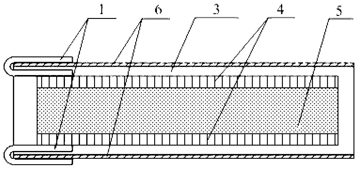
[0036] Deposit a 3um thick dense oxide coating 6 (aluminum oxide, silicon oxide or titanium oxide, etc.) on the surface of the pre-packaged photo-curing coating 3 of the driver using a normal temperature magnetron sputtering process, place the target and the IPMC material driver, and adjust Magnetron sputtering process parameters: vacuum degree 2×10 -5 torr, power supply 200W, argon gas rate 20sccm; other steps are the same as in Example 1. After encapsulation, get as figure 2 structure shown.

Embodiment 3

[0038] Photocuring adhesive bonding high barrier material IPMC driver package

[0039] (1) Make the IPMC driver and connect the lead electrodes

[0040] Same as step (1) in Example 1.

[0041] (2) Using UV-curable coatings as the adhesive, using the model H-Barrier produced by Mitsubishi, with a thickness of 10um as the upper and lower barrier base film, and using the N-Barrier produced by Norland O A74 light-curing glue is coated on the inner layer of the upper and lower base films, and the glue coating area should cover the upper and lower surfaces of the IPMC driver, and the inner layer of the upper and lower barrier base films is pasted on the upper and lower surface electrodes of the IPMC driver (including the connection with the initial lead-out electrode) , and apply pressure to the outer layers of the upper and lower barrier base films to make the encapsulation layer thin and flat.

[0042](3) Put the whole driver under a UV lamp and treat the front and back sides fo...


PUM

PropertyMeasurementUnit
Thicknessaaaaaaaaaa

Abstract

The invention discloses a packaging process capable of improving the stability of an ionic polymer metal composite (IPMC) driver. The packaging process is characterized in that the packaging process is implemented by two methods, wherein one method comprises the steps of performing pre-packaging by using an ultraviolet gluing material, and depositing a Parylene coating or a gas barrier layer such as a dense oxide gas barrier layer at normal temperature; and the other method comprises the step of adhering an IPMC surface to a high-barrier thin film material by using light curing glue as an adhesive, so that the stability of water in the material is ensured. According to the packaging process, the curing time of a packaging layer is greatly reduced; in addition, heating is not required in the whole process, so that the water in the material can be accurately controlled; and the packaging process has high practical value.

Description

technical field [0001] The invention relates to a preparation method of an IPMC driver, in particular to a packaging process of the IPMC driver. Background technique [0002] Ionic polymer-metal composites (IPMC) have light weight, good flexibility, rapid response, and bidirectional reversible functions of sensing and actuation, and can be used to make electromechanical transducers such as drivers that generate large deformations to replace traditional piezoelectric Ceramics are new intelligent materials that have emerged in the past two decades and have great application potential. [0003] When IPMC is directly used as a driver, there are two obvious defects: on the one hand, the IPMC driver deforms rapidly under the action of DC voltage, and at the same time has reverse relaxation phenomenon; on the other hand, the IPMC driver itself contains certain moisture and cannot be used for a long time Work in the air, otherwise the performance will gradually decay due to slow lo...

Claims


Application Information

Patent Timeline
IPC IPC(8): H01L41/23
Inventor 陈花玲朱子才罗斌王延杰常龙飞
Owner XI AN JIAOTONG UNIV
Why Eureka
Try Eureka