
Method and apparatus for digital control of a lighting device

a lighting device and digital control technology, applied in the field of digital control of lighting devices, can solve the problems of affecting the output of the system, affecting the performance of the system, and affecting the operation of the lighting device, and achieving the effect of avoiding overshoot and oscillation

Active Publication Date: 2008-07-10
KONINKLIJKE PHILIPS ELECTRONICS NV
View PDF57 Cites 38 Cited by
  • Summary
  • Abstract
  • Description
  • Claims
  • Application Information

AI Technical Summary

Benefits of technology

[0011]An object of the present invention is to provide a method and apparatus for digital control of a lighting device. In accordance with an aspect of the present invention, there is provided a method of digital control of a lighting device using a PID controller, the method comprising the steps of: obtaining a desired lighting device operational set point; determining a present lighting device operational point; determining a relationship based at least: in part on the desired lighting device operational set point, the present lighting device operational point or both and comparing the relationship to a predetermined threshold; assigning a first set of values as PID controller parameters when the relationship is above the predetermined threshold; assigning a second set of values as PID controller parameters when the relationship is above the predetermined threshold; and controlling the lighting device using the PID controller with the assigned PID controller parameters.

Problems solved by technology

This can be performed however at the expense of potential overshoot and oscillation at the desired set point.
In some systems this can result in a noticeable and undesired variation in the output of the system.
A problem with this configuration is that for a system which produces undesired and noticeable changes in output may require that the desired set point is reached in a more rapid manner.
This, however, is typically not a simple solution to the problem.
For example and having specific regard to the use of PID controllers with solid state lighting, a specific problem occurs when controlling the output of the luminaire at low intensity levels, whether it be a change in colour, colour temperature or a change in intensity.
When changing the intensity, or controlling the intensity of a luminaire at relatively high light outputs, overshoot beyond, or oscillation about the desired set point by a few intensity steps is typically not perceivable to the eye.
This degree of overshoot and oscillation about a desired set point is typically readily perceivable and can be annoying to some viewers.
This relationship results in a perceived non-linear brightness when using linear control parameters.

Method used


Image

  • Method and apparatus for digital control of a lighting device
  • Method and apparatus for digital control of a lighting device
  • Method and apparatus for digital control of a lighting device

Examples


examples

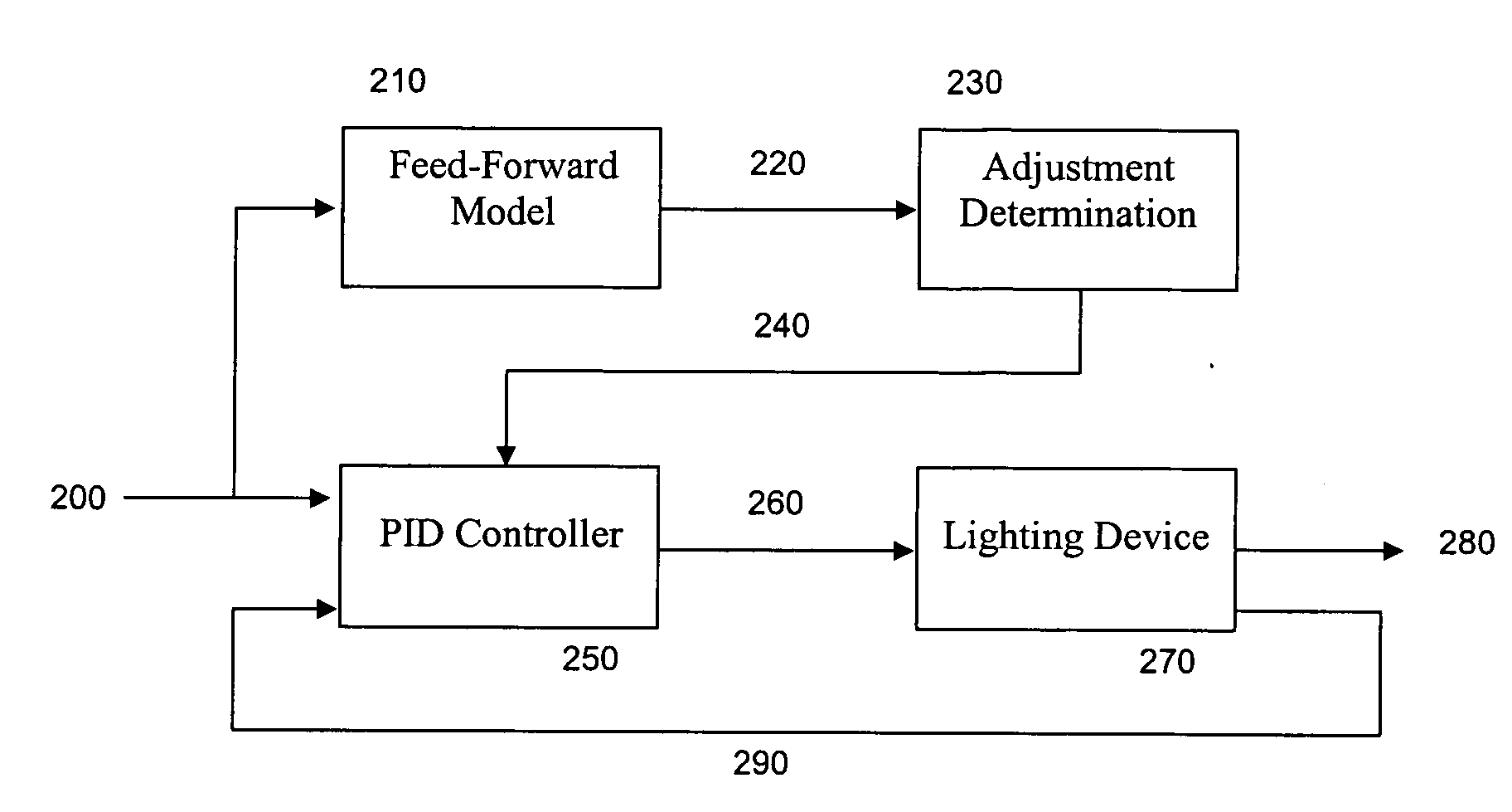
[0052]FIG. 5 illustrates the architecture of a feedback and control system for a luminaire or solid-state lighting device which comprises the method and apparatus for digital control according to one embodiment of the present invention. The luminaire comprises one or more light-emitting elements 40 for the generation of light, wherein the light-emitting elements 40 are electrically connected to the power supply 30 via the current drivers 35. The power supply 30 can be for example, based on an AC / DC or DC / DC converter. If there are multiple colours of light-emitting elements, separate current drivers 35 can be provided for each colour, thereby enabling the supply of the necessary forward currents to each of the colours of light-emitting elements 40.

[0053]One or more light sensors 50 are provided for detecting luminous flux output from the luminaire. In one embodiment, separate light sensors 50 are provided for each colour of the light-emitting elements 40. In addition, a colour filte...


PUM


Abstract

The present invention provides a method and apparatus for digitally controlling a lighting device which enables a desired lighting device operational set point to be reached in a rapid manner while substantially reducing overshoot and oscillation about the desired lighting device operational set point. In particular the present invention is enabled by a PID controller configured to vary the PID controller parameters based on a relationship based at least in part on the desired lighting device operational set point, the present lighting device operational point or both.

Description

RELATED APPLICATIONS[0001]This application claims the benefit of priority under 35 U.S.C. §119(e) to U.S. provisional application Ser. No. 60 / 869,534, filed Dec. 11, 2006, the subject matter of which is herein incorporated by reference in its entirety.FIELD OF THE INVENTION[0002]The present invention pertains to the field of control of devices and in particular to digital control of lighting devices, for example solid-state light sources.BACKGROUND[0003]It is generally known that the transient behaviour of proportional-integral-derivative (PID) controlled systems can be classified into a number of different categories. Depending on the amplitudes, generally referred to as the PID parameters, at which each of the proportional, integral and derivative signals are being amplified by the controller, the output of the system can reach the desired set point in a number of different manners. For example the desired set point can be reached rapidly with some degree of overshoot before settl...

Claims


Application Information

Patent Timeline
Patent Type & Authority Applications(United States)
IPC IPC(8): G05B13/02H05B44/00
CPCG05B11/42H05B33/0869H05B33/086G05B13/024H05B45/22H05B45/28G05B11/36H05B45/20
Inventor ROBINSON, SHANE P.POLI, STEFAN
Owner KONINKLIJKE PHILIPS ELECTRONICS NV
Features
  • Generate Ideas
  • Intellectual Property
  • Life Sciences
  • Materials
  • Tech Scout
  • Unparalleled Data Quality
  • Higher Quality Content
  • 60% Fewer Hallucinations
Learn More