

Vane Diffuser
- Summary
- Abstract
- Description
- Claims
- Application Information
AI Technical Summary
Benefits of technology
Problems solved by technology
Method used
Image

Examples
Example
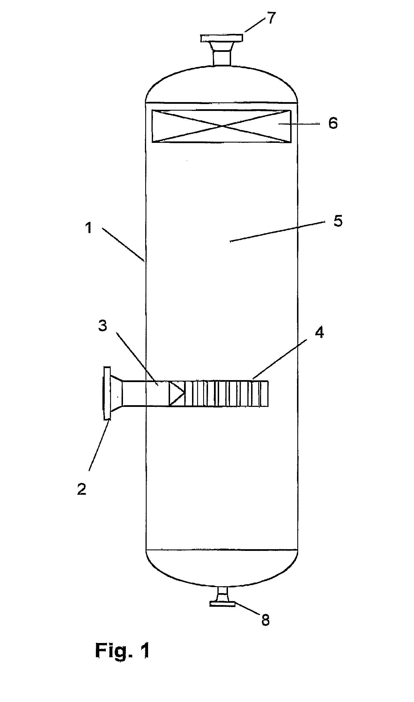
[0022]FIG. 1 shows a separator according to prior art technology comprising a tank 1, an inlet pipe stub 2, a communication channel 3 which communicates with a vane diffuser inlet assembly 4 which is intended to receive, retard and distribute inflowing gas and liquid from the pipe stub 2 as gently as possible into the separator's settling zone 5. The settling zone 5 is usually relatively small so settling of small droplets by means of gravity takes place only to in a quite limited extent. It is therefore preferred that the vane diffuser 4 is designed in a manner to take out most of the liquid in the gas flow immediately after the latter enters the separator. This is not well taken care of in vane diffusers 4 according to prior art technology. The gas passing through zone 5 will hold many small and some medium sizes drops when entering the demister equipment 6 where additional liquid drops are separated out. The demisted gas is discharged from the separator through upper outlet pipe ...
PUM
| Property | Measurement | Unit |
|---|---|---|
| Fraction | aaaaa | aaaaa |
| Length | aaaaa | aaaaa |
| Thickness | aaaaa | aaaaa |
Abstract
Description
Claims
Application Information