Method and Apparatus for Fluid Bypass of a Well Tool

a well tool and fluid bypass technology, applied in the field of subsurface apparatuses, can solve the problems of obstructing the deployment of capillary tubing strings to subterranean production zones, obstructing the deployment of capillary tubing strings, and occupying spa

Active Publication Date: 2008-07-17
BAKER HUGHES INC
View PDF6 Cites 35 Cited by
  • Summary
  • Abstract
  • Description
  • Claims
  • Application Information

AI Technical Summary

Benefits of technology

[0012]The deficiencies of the prior art are also addressed by an anchor seal assembly to be deployed inside a string of production tubing. The anchor seal assembly includes a main body providing an upper connection to an upper injection conduit, an engagement profile, and a lower connection to a lower injection conduit. The anchor seal assembly preferably includes a downhole production component housed within the main body wherein a pathway extending through the main body is diverted around the downhole production component to connect the upper and lower connections. Preferably, the engagement profile is configured to be retained within a landing profile located within the string of production tubing. The anchor seal assembly also preferably includes an actuation conduit to operate the downhole production component and a seal assembly to seal an interface between the string of production tubing and the main body. The anchor se...

Problems solved by technology

Various obstructions exist within strings of production tubing in subterranean wellbores.
Valves, whipstocks, packers, plugs, sliding side doors, flow control devices, expansion joints, on/off attachments, landing nipples, dual completion components, and other tubing retrievable completion equipment can obstruct the deployment of capillary tubing strings to subterranean production zones.
Particularly, in circumstances where stimulation operations are to be performed on non-producing hydrocarbon wells, the obstructions stand in the way of operations that are capable of obtaining continued production out of a well long considered “depleted.” Most depleted wells are not lacking in hydrocarbon reserves, rather the natural pressure of the hydrocarbon producing zone is so low that it fails to overcome the hydrostatic pressure or ...

Method used


Image

  • Method and Apparatus for Fluid Bypass of a Well Tool
  • Method and Apparatus for Fluid Bypass of a Well Tool
  • Method and Apparatus for Fluid Bypass of a Well Tool

Examples


Embodiment Construction

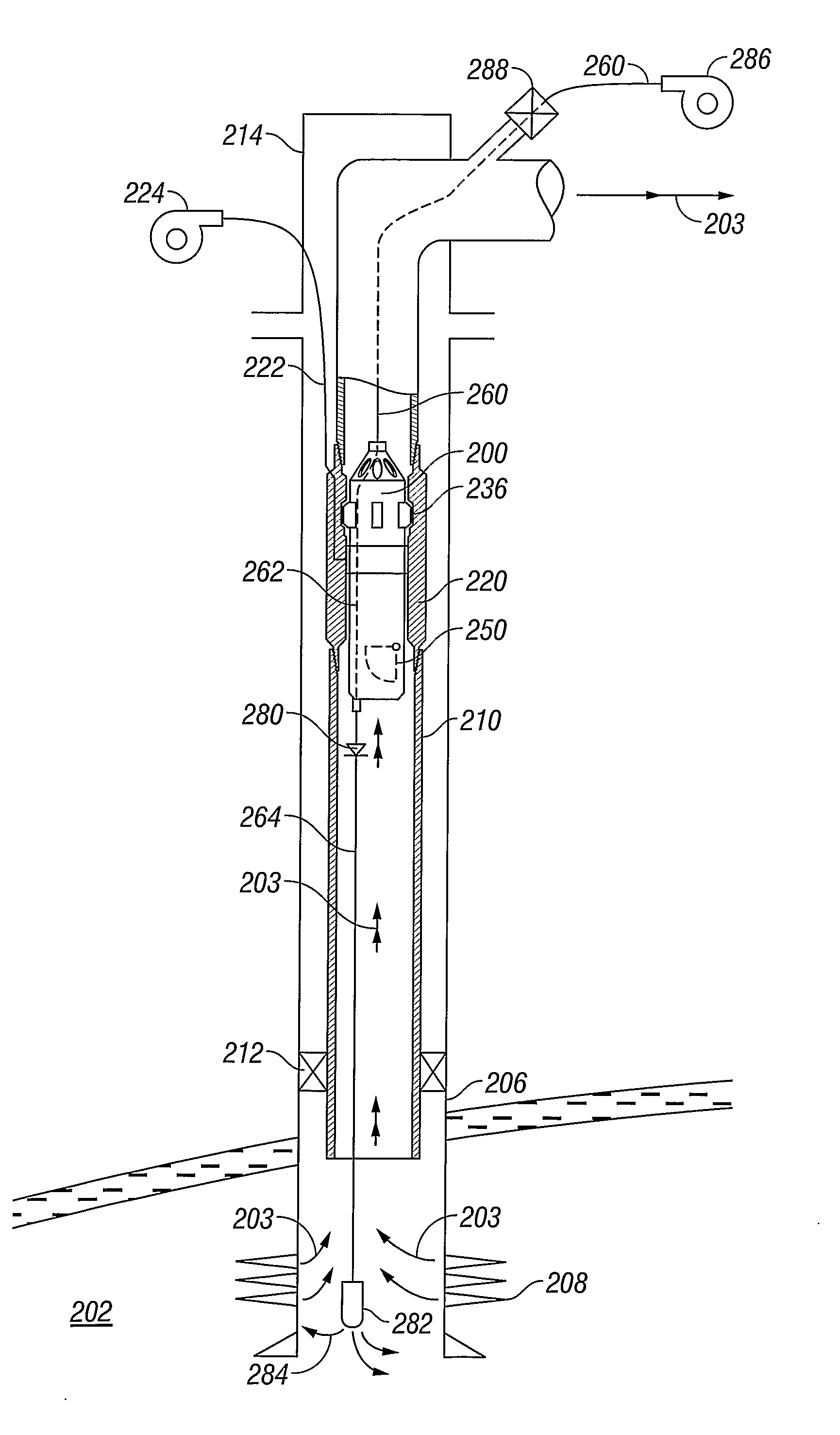
[0017]Referring initially to FIG. 1, a well production system 100 is shown schematically. Normally, well production system 100 allows for the recovery of production fluids (hydrocarbons) from an underground reservoir 102 to a location on the surface 104. To retrieve the production fluids, a cased borehole 106 is drilled from the surface 104 to reservoir 102. Perforations 108 allow the flow of production fluids from reservoir 102 into cased borehole 106 where reservoir pressure pushes them to the surface 102 through a string of production tubing 110. A packer 112 preferably seals the annulus between production tubing 110 and cased borehole 106 to prevent the pressurized production fluids from escaping through the annulus. A wellhead 114 caps the upper end of the cased wellbore 106 to prevent annular fluids from escaping into and polluting the environment. Preferably, wellhead 114 provides sealed ports 116 where strings of tubing (for example, production tubing 110) are allowed to pas...


PUM


Abstract

Apparatuses and methods to inject chemical stimulants (284) to a production zone (102, 202) through a string of production tubing (110, 210) around a downhole obstruction are disclosed. The apparatuses and methods include deploying an anchor seal assembly (200) to a landing profile (120, 220) located within a string of production tubing (110, 210). The anchor seal assembly (200) is in communication with a surface station through an injection conduit (260, 264) and includes a bypass pathway (262) to inject various fluids to a zone below.

Description

CROSS-REFERENCE TO RELATED APPLICATION[0001]This application claims the benefit of provisional application U.S. Ser. No. 60 / 593,216 filed Dec. 22, 2004.BACKGROUND OF THE INVENTION[0002]The present invention generally relates to subsurface apparatuses used in the petroleum production industry. More particularly, the present invention relates to an apparatus and method to conduct fluid through subsurface apparatuses, such as a subsurface safety valve, to a downhole location. More particularly still, the present invention relates to apparatuses and methods to install a subsurface safety valve incorporating a bypass conduit allowing communications between a surface station and a lower zone regardless of the operation of the safety valve.[0003]Various obstructions exist within strings of production tubing in subterranean wellbores. Valves, whipstocks, packers, plugs, sliding side doors, flow control devices, expansion joints, on / off attachments, landing nipples, dual completion component...

Claims


Application Information

Patent Timeline
IPC IPC(8): E21B34/10
CPCE21B34/106E21B2034/005E21B43/25E21B2200/05
Inventor HILL, THOMAS GBOLDING, JEFFREY L.SMITH, DAVID R.
Owner BAKER HUGHES INC
Why Eureka
Try Eureka