
Collapsible container

a container and collapsible technology, applied in the field of folding containers, can solve the problem that pockets require a longer pull

Inactive Publication Date: 2008-07-17
MARAZITA NICK +1
View PDF40 Cites 91 Cited by
  • Summary
  • Abstract
  • Description
  • Claims
  • Application Information

AI Technical Summary

Benefits of technology

[0017]Three snap hinges extend downward from the bottom edges of the left and right panels. Three snap sockets are disposed in each of the base left and right sides. Each snap socket receives one of the snap hinges. Each snap socket has a predetermined width. Two novel trunnions project outward from each snap hinge. The trunnions are eccentric to decrease the backlash between the snap hinge and the snap socket with the panels in the open position, to locate the panels precisely. Conversely, the trunnions will increase the backlash with the panels in the closed position, to allow for easy folding of the panels.
[0022]Feet extend downward from the base to a bottom surface to raise the container off a floor. The feet have shoulders to receive the top edges of the panels when the container is open. The shoulders will receive the base wall when the container is folded, to enable containers to be stacked one upon another in both the open and closed conditions. Skid bars are attached to the feet. Bumper plates, mounted on the feet outer edges, have flanges that prevent the container from shifting on an adjacent lower stacked container.

Problems solved by technology

Furthermore, the pockets require a longer pull to open the mold to eject the finished base.
Yet, the hinge joints are all made close fitting, so that as the panels are pivoted downward, they may not nest precisely in the base.

Method used


Image

  • Collapsible container
  • Collapsible container
  • Collapsible container

Examples


Embodiment Construction

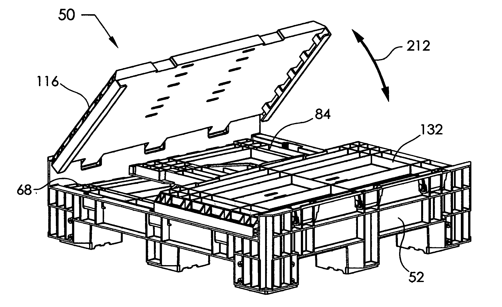
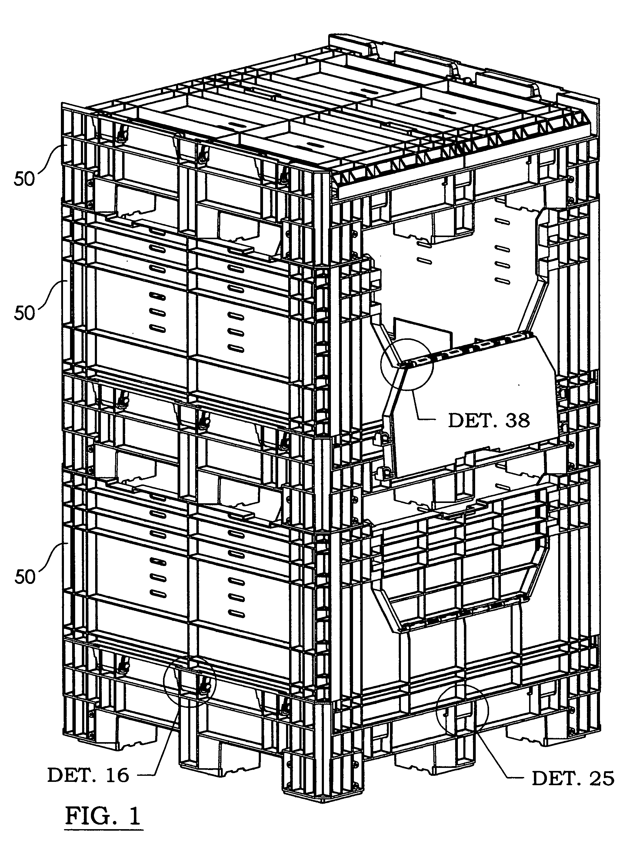
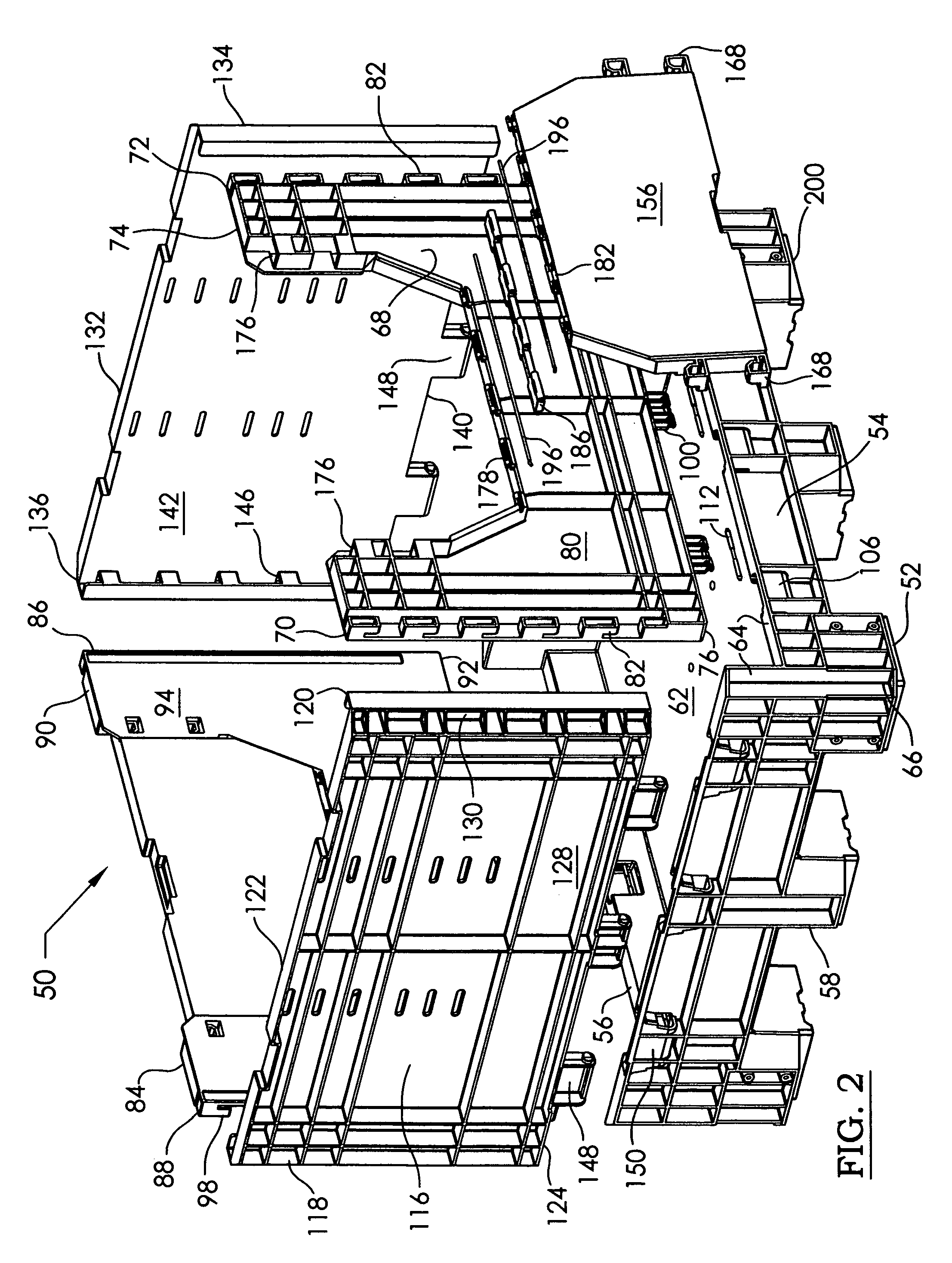
[0076]Referring now to the drawing, and especially to FIGS. 1-32 thereof, a collapsible container is shown at 50, and is for use in conveying and storing bulk material and products. A base 52 extends between opposite front 54 and rear 56 ends, and between opposite left 58 and right 60 sides. The base 52 has a floor 62 extending between the base front 54 and rear 56 ends and between the base left 58 and right 60 sides. The base 52 has a wall 64 extending along the front 54 and rear 56 ends and the left 58 and right 60 sides. The wall 64 projects upward above the floor 62. The base 52 has four corners 66 where the ends meet the sides. FIG. 3 is a top plan view of the base, showing the floor 62 being continuous, with no large openings to trap bulk material, and only a few small drain holes 63. FIG. 6 is a bottom view of FIG. 3, showing the reinforcing structure.

[0077]A front panel 68 extends between opposite first 70 and second 72 edges and between opposite top 74 and bottom 76 edges. ...


PUM


Abstract

A collapsible container has four panels that fold down on a base for storage. The base has slide sockets with vertical slots. Front and rear panels pivot on the base with slide hinges received in the slide sockets. The panels are able to slide up and down. A hinge pin has a narrowed waist portion to engage a latch. Left and right panels pivot with snap hinges received in snap sockets on the base. Trunnions, disposed in the snap sockets, are eccentric to increase or decrease the backlash between the snap hinge and the snap socket as the panels pivot. The left and right panels have edge pockets that receive edge fingers on the front and rear panels to hold the container open. The front and rear panels each have an access opening with access doors. Links pivot the access doors on two hinge rods. Locking members wedge the hinge rods in the hinge knuckles. The base has feet with bumper plates having flanges that prevent the container from shifting on an adjacent lower stacked container.

Description

CROSS-REFERENCE TO RELATED APPLICATIONS[0001]Not ApplicableSTATEMENT REGARDING FEDERALLY SPONSORED RESEARCH OR DEVELOPMENT[0002]Not ApplicableBACKGROUND OF THE INVENTION[0003]This invention relates to the field of folding containers, and more particularly to a—bulk material container having side and end panels pivotally mounted to a base, and able to fold down upon the base. For shipping or storing the empty container, the panels are folded down flat. To open the container for use, the panels are pivoted upright and locked together at the corners. Open containers filled with bulk material can be stacked one upon another. Folded containers can be stacked for efficient shipping and storage. Mixed open and folded containers can also be stacked.[0004]Collapsible containers are known in the prior art, and have taken a variety of configurations in the past. Some examples of collapsible containers are as follows:[0005]Miller, U.S. Pat. No. 5,094,356; Reiland, U.S. Pat. No. 4,775,068; Fried...

Claims


Application Information

Patent Timeline
IPC IPC(8): B65D6/18B65D21/02B65D19/06B65D19/18
CPCB65D19/18B65D2519/00975B65D2519/00069B65D2519/00174B65D2519/00268B65D2519/00278B65D2519/00288B65D2519/00318B65D2519/00338B65D2519/00402B65D2519/00422B65D2519/00497B65D2519/00502B65D2519/00587B65D2519/00656B65D2519/008B65D2519/00805B65D2519/009B65D2519/00034
Inventor MARAZITA, NICKJENSEN, GUY
Owner MARAZITA NICK
Learn More