Composite aircraft window frame

a window frame and composite technology, applied in the field of composite aircraft window frames, can solve the problems of cost of commercial aircraft operation

Inactive Publication Date: 2008-07-17
NORDAM GROUP
View PDF36 Cites 78 Cited by
  • Summary
  • Abstract
  • Description
  • Claims
  • Application Information

AI Technical Summary

Problems solved by technology

Furthermore, the cost of commercial aircraft operation is a paramount de

Method used


Image

  • Composite aircraft window frame
  • Composite aircraft window frame
  • Composite aircraft window frame

Examples


Embodiment Construction

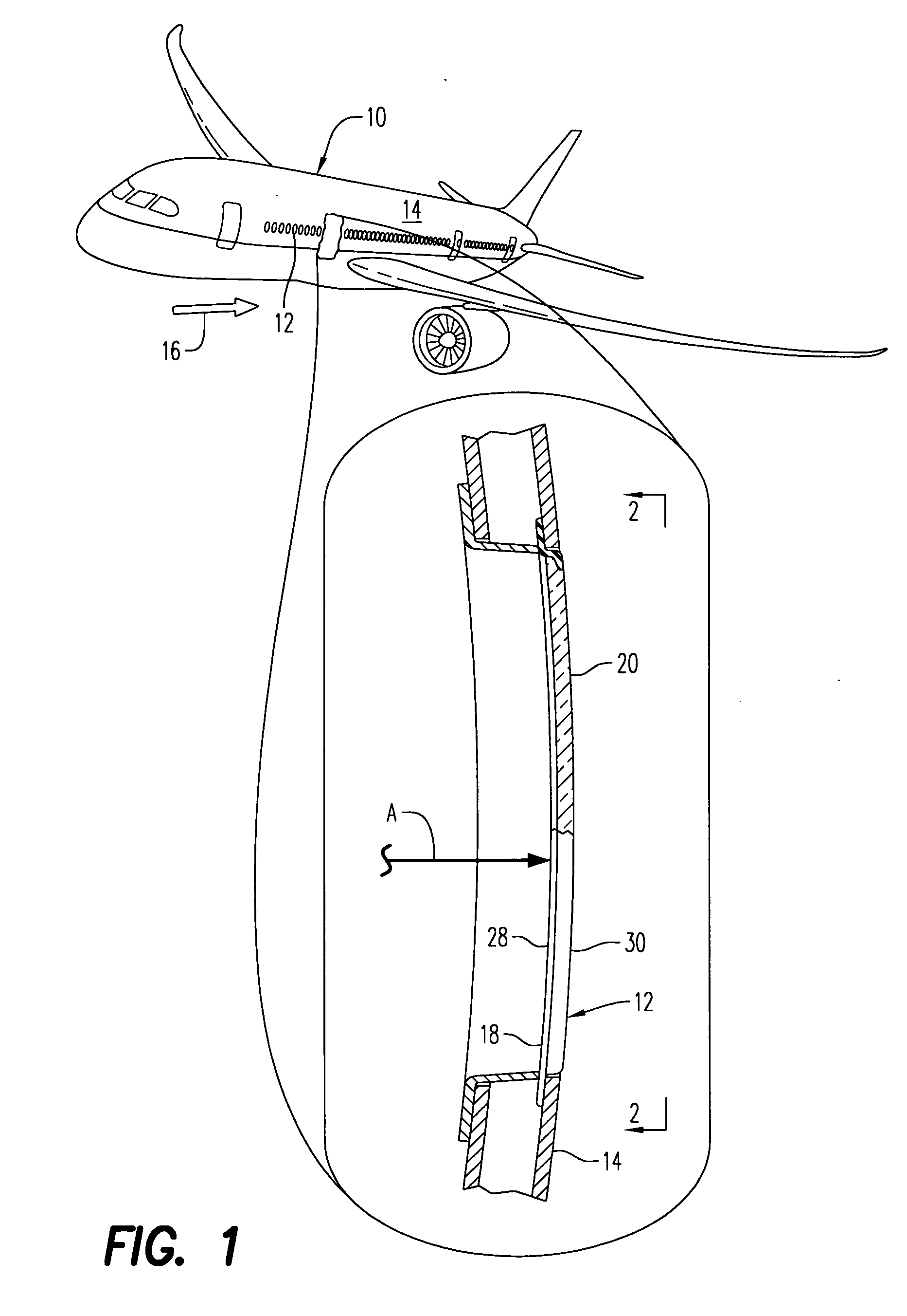
[0019]FIG. 1 illustrates an exemplary airplane or aircraft 10 powered by gas turbofan engines in flight. The aircraft includes numerous windows 12 arranged in rows along both sides of the fuselage or outer skin 14 from the forward cockpit end of the aircraft to just before the aft tail.

[0020]The windows maintain the pressure integrity of the cabin and protect the passengers therein from the external environment, including the fast stream of external air 16 flowing aft over the outer skin during aircraft flight.

[0021]Each window is suitably mounted through a corresponding aperture in the aircraft skin 14, and the windows vary in size and configuration along the length of the aircraft. Since the fuselage 14 is generally cylindrical or tubular it has an internal diameter, or radius A which varies along the length of the aircraft from the sharp nose, through the wide passenger body, and to the sharp tail.

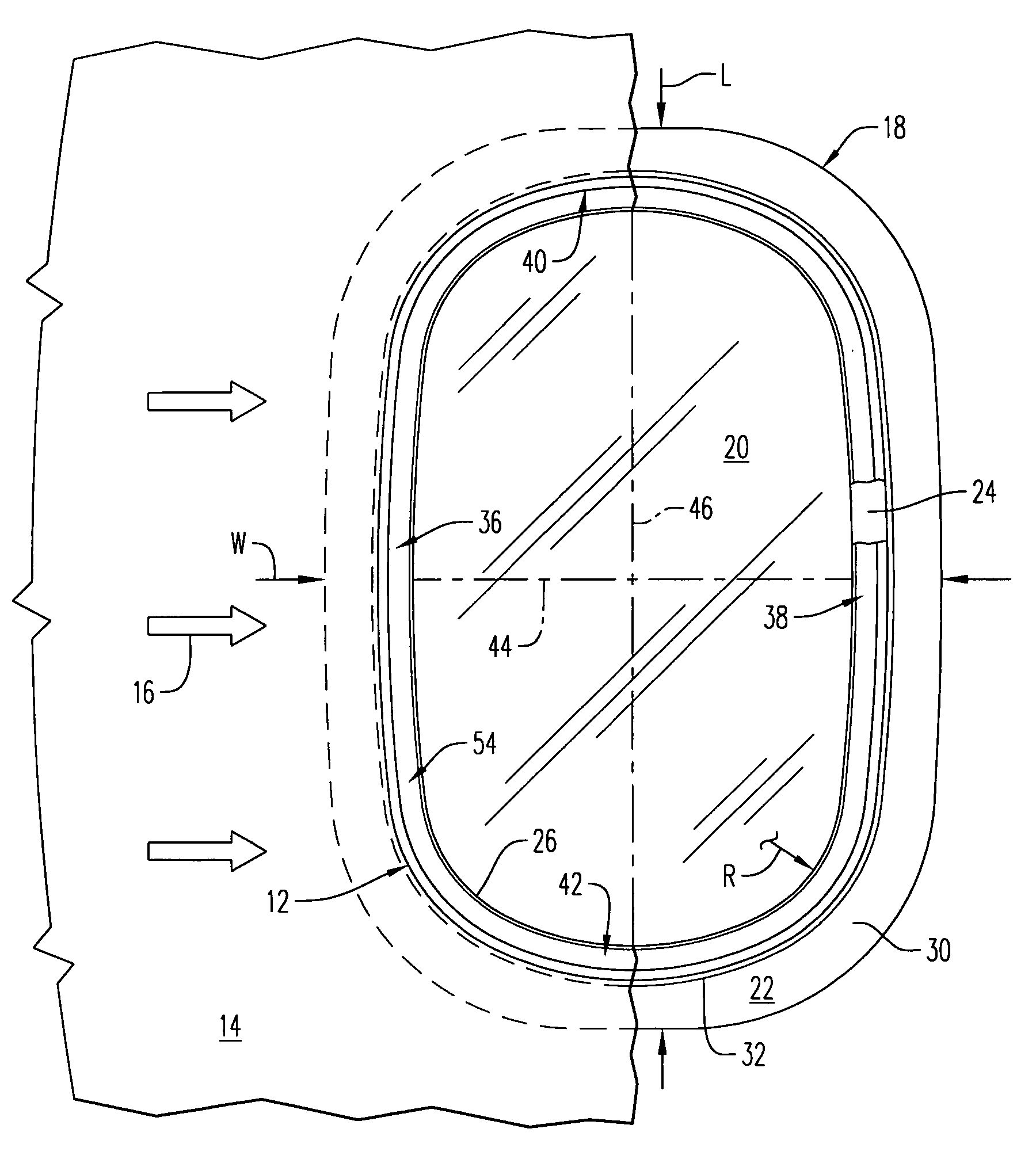
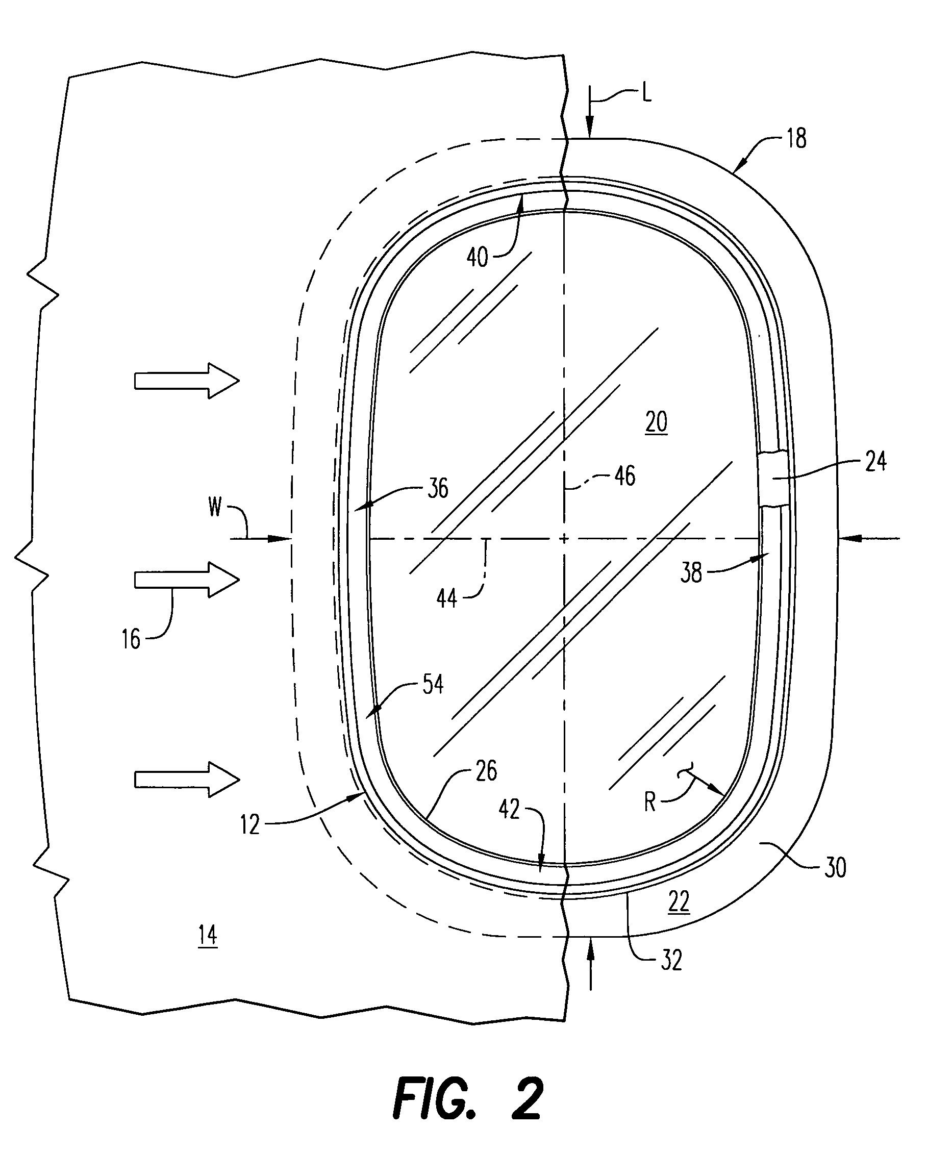
[0022]Each window 12 is specifically sized and configured to match the local curvat...


PUM

PropertyMeasurementUnit
Weightaaaaaaaaaa
Thicknessaaaaaaaaaa
Pressureaaaaaaaaaa

Abstract

An aircraft window frame includes a laminated outer rim and inner sash having a central aperture for receiving a window pane. The sash is transversely offset from the rim and they include different layers between the opposite inboard and outboard sides of the frame.

Description

[0001]This application claims the benefit of U.S. Provisional Application No. 60 / 880,100; filed Jan. 12, 2007.BACKGROUND OF THE INVENTION[0002]The present invention relates generally to aircraft, and, more specifically, to windows therein.[0003]In the typical commercial aircraft, numerous windows are distributed along both sides of the fuselage from the cockpit aft to just before the tail. The fuselage is tubular and varies in diameter or radius between the forward and aft ends of the aircraft, and correspondingly the size and curvature of the windows also vary along the length of the aircraft.[0004]Each window includes a frame suitably mounted in a corresponding aperture in the external skin of the aircraft, and each frame securely mounts therein a corresponding window pane.[0005]Typical aircraft skins are made of high strength metal, such as aluminum, and the typical window frame is also made of high strength metal. Various metal fabrication methods are therefore used to fabricate...

Claims


Application Information

Patent Timeline
IPC IPC(8): B64C1/14
CPCB64C1/1492B29C70/345B29C70/462B29L2031/005B29C70/304Y02T50/40
Inventor JACKSON, KEVIN STEVENWALLACE, STEPHEN FREDERICK JOSEPHOSTREM, SCOTT ERNEST
Owner NORDAM GROUP
Why Eureka
Try Eureka