Sound outputting apparatus, sound outputting method, sound outputting system and sound output processing program

a sound output and audio output technology, applied in the direction of stereophonic circuit arrangements, gain control, ear moulds/tips acoustic seals, etc., can solve the problems of listener not being conscious, listener not being able to realize the fundamental solution, and listener raising the sound volum

Inactive Publication Date: 2008-07-17
SONY CORP
View PDF6 Cites 45 Cited by
  • Summary
  • Abstract
  • Description
  • Claims
  • Application Information

AI Technical Summary

Benefits of technology

[0016]With the sound outputting apparatus, the surrounding noise evaluation section evaluates the state of the surrounding noise outside the housing based on the second sound signal from the sound collection section. Therefore, it can be decided and evaluated, for example, whether the surrounding environment outside the housing is an environment wherein the surrounding noise is small and leaking sound is likely to be felt as noise or disagreeable sound by the other pe

Problems solved by technology

However, where an audio player does not have such a compressor processing function or a limiter function as disclosed in Patent Document 1, the fundamental solution may not be reached unless the listener narrows down the sound volume and listens to reproduction sound with a small sound volume.
Incidentally, the listener actually raises the sound volume in most cases where the surrounding environment (listening environment) at a site at which the listener listens is noisy because of noise.
However, in this instance, since the listen

Method used


Image

  • Sound outputting apparatus, sound outputting method, sound outputting system and sound output processing program
  • Sound outputting apparatus, sound outputting method, sound outputting system and sound output processing program
  • Sound outputting apparatus, sound outputting method, sound outputting system and sound output processing program

Examples


first embodiment

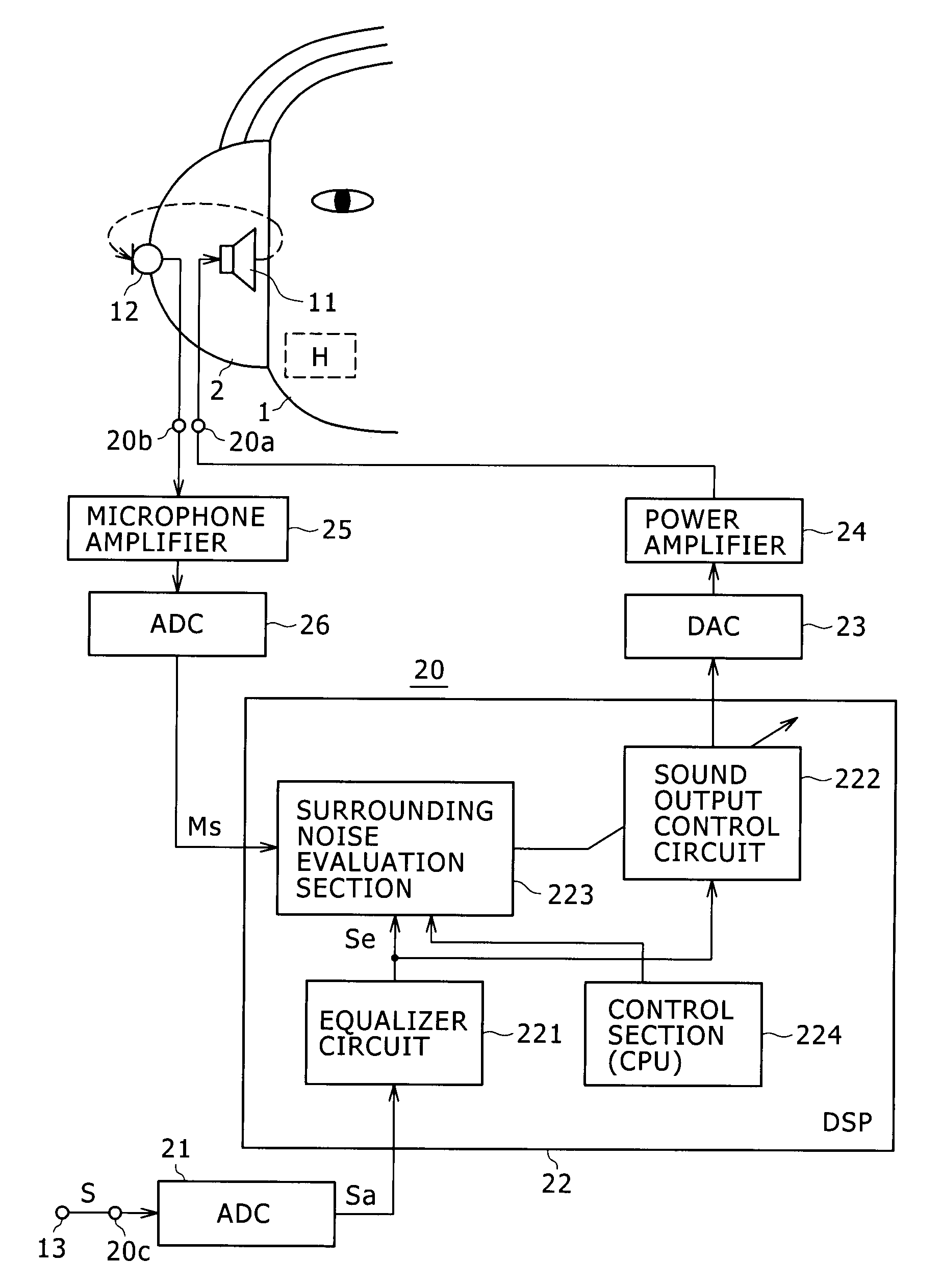
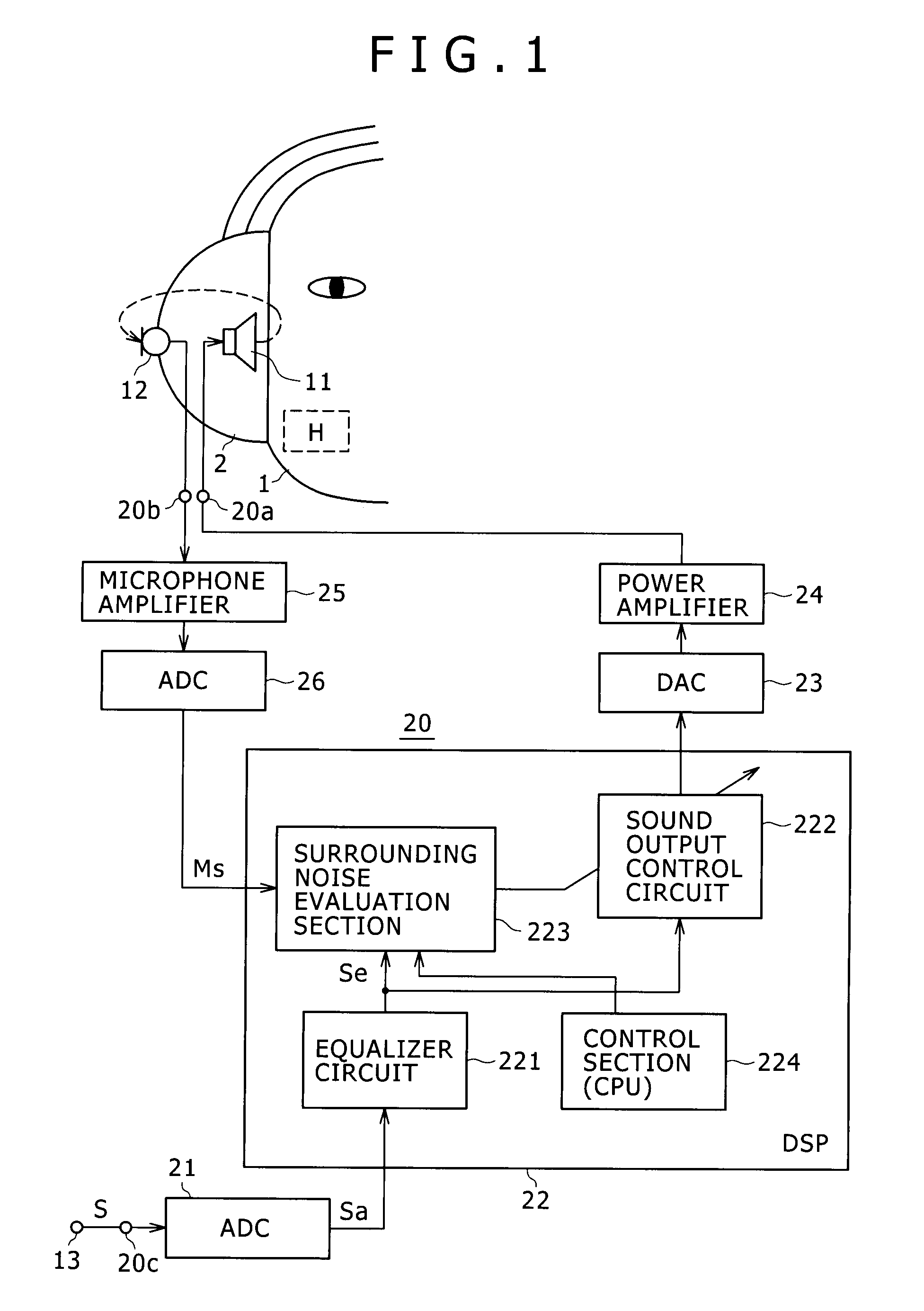
[0023]FIG. 1 shows an example of a configuration of a first embodiment of the present invention wherein a sound outputting apparatus of the present invention is applied to a headphone apparatus.

[0024]In FIG. 1, a configuration only of a portion of the headphone apparatus for the right ear side of a listener 1 is shown for simplified illustration. This similarly applies to the other embodiments hereinafter described. Naturally, also the other portion of the headphone apparatus for the left ear side of the listener 1 is configured similarly.

[0025]Referring first to FIG. 1, the headphone apparatus is mounted on the listener 1 such that the right ear of the listener 1 is covered with a headphone housing (housing section) 2 for the right ear. A headphone driver unit (hereinafter referred to simply as driver) 11 is provided on the inner side of the headphone housing 2 and serves as an electroacoustic conversion section for acoustically reproducing a sound signal in the form of an electric...

first example

[0059]FIG. 3 shows a first example of a configuration of the surrounding noise evaluation section 223. Referring to FIG. 3, the surrounding noise evaluation section 223 shown includes a difference value calculation section 31, a difference value decision section 32, a control signal production section 33 and an H′ multiplication circuit 34.

[0060]Where the transfer function from the driver 11 in the housing 2 to the microphone 12 outside the housing 2 is represented by H as seen in FIG. 1, when reproduction sound acoustically reproduced by the driver 11 leaks to the outside from within the housing 2, it can be estimated using the transfer function H what time waveform is indicated at the position of the microphone 12.

[0061]In the present embodiment, while the surrounding noise evaluation section 223 removes a leaking sound component of acoustic reproduction sound of the sound signal Se to the outside of the housing 2 from the digital sound signal Ms, the signal to be removed is not t...

second example

[0075]FIG. 4 shows a second example of the configuration of the surrounding noise evaluation section 223. The surrounding noise evaluation section 223 shown in FIG. 4 converts the digital sound signal Ms and the signal Se′ from signals in the time domain into signals in the frequency domain such that the subtraction between the signals Ms and Se′ is performed in the frequency region to determine a difference value.

[0076]Referring to FIG. 4, in the present second example, the surrounding noise evaluation section 223 includes an H′ multiplication circuit 34, a pair of FFT processing circuits 35 and 36, a frequency amplitude difference value calculation section 37, a frequency amplitude difference value decision section 38, and a control signal production circuit 39.

[0077]The FFT processing circuit 35 converts the digital sound signal Ms, for example, within the prescribed interval from a signal in the time domain into another signal in the frequency domain, and supplies the signal Ms_...


PUM


Abstract

Disclosed herein is a sound outputting apparatus, including: an electro-acoustic conversion section disposed in a housing and configured to acoustically reproduce a first sound signal; a sound collection section configured to collect sound outside said housing and output a second sound signal; a surrounding noise evaluation section configured to evaluate surrounding noise outside said housing based on the second electric signal; and a control section configured to perform predetermined control based on a result of the evaluation of said surrounding noise evaluation section.

Description

CROSS REFERENCES TO RELATED APPLICATIONS[0001]The present invention contains subject matter related to Japanese Patent Application JP 2007-006504 filed in the Japan Patent Office on Jan. 16, 2007, the entire contents of which being incorporated herein by reference.BACKGROUND OF THE INVENTION[0002]1. Field of the Invention[0003]This invention relates to a sound outputting apparatus such as a headphone apparatus and a portable telephone terminal and also to a sound outputting method and a sound output processing program for use with the apparatus as well as a sound outputting system which includes a headphone apparatus and a sound outputting apparatus.[0004]2. Description of the Related Art[0005]In order to acoustically reproduce a reproduction sound signal of a portable audio player so that a listener listens to the sound, usually a headphone apparatus or an earphone apparatus is used such that sound may not leak to the outside.[0006]However, sound leaking from a headphone apparatus ...

Claims


Application Information

Patent Timeline
IPC IPC(8): H03G3/00
CPCH04R1/1041H04R5/033H04R5/04H04R2460/15
Inventor ASADA, KOHEIKAWANISHI, HIROKI
Owner SONY CORP
Why Eureka
Try Eureka