
Bone anchor manipulation device

Inactive Publication Date: 2008-07-17
DEPUY SPINE INC (US)
View PDF18 Cites 112 Cited by
  • Summary
  • Abstract
  • Description
  • Claims
  • Application Information

AI Technical Summary

Benefits of technology

[0003]Disclosed herein are instruments and methods for manipulating a bone anchor an in turn a vertebral body to which it is attached. The instruments and method

Problems solved by technology

This stress can cause a failure of one or more of the bone anchors or vertebrae.

Method used


Image

  • Bone anchor manipulation device
  • Bone anchor manipulation device
  • Bone anchor manipulation device

Examples


Embodiment Construction

[0024]Certain exemplary embodiments will now be described to provide an overall understanding of the principles of the structure, function, manufacture, and use of the instruments and methods disclosed herein. One or more examples of these embodiments are illustrated in the accompanying drawings. Those of ordinary skill in the art will understand that the instruments and methods specifically described herein and illustrated in the accompanying drawings are non-limiting exemplary embodiments and that the scope of the present invention is defined solely by the claims. The features illustrated or described in connection with one exemplary embodiment may be combined with the features of other embodiments. Such modifications and variations are intended to be included within the scope of the present invention.

[0025]The articles “a” and “an” are used herein to refer to one or to more than one (i.e. to at least one) of the grammatical object of the article. By way of example, “an element” m...


PUM


Abstract

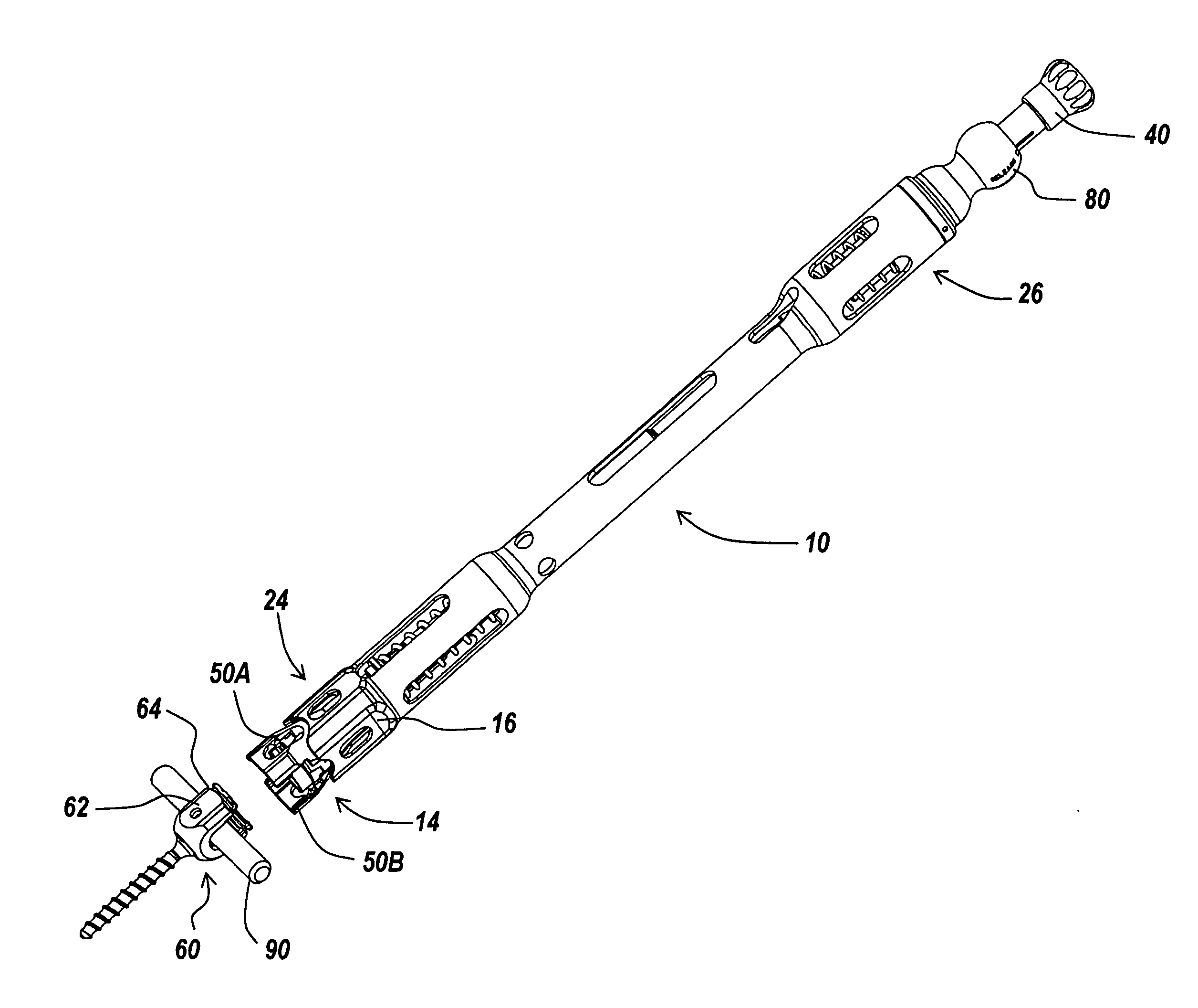
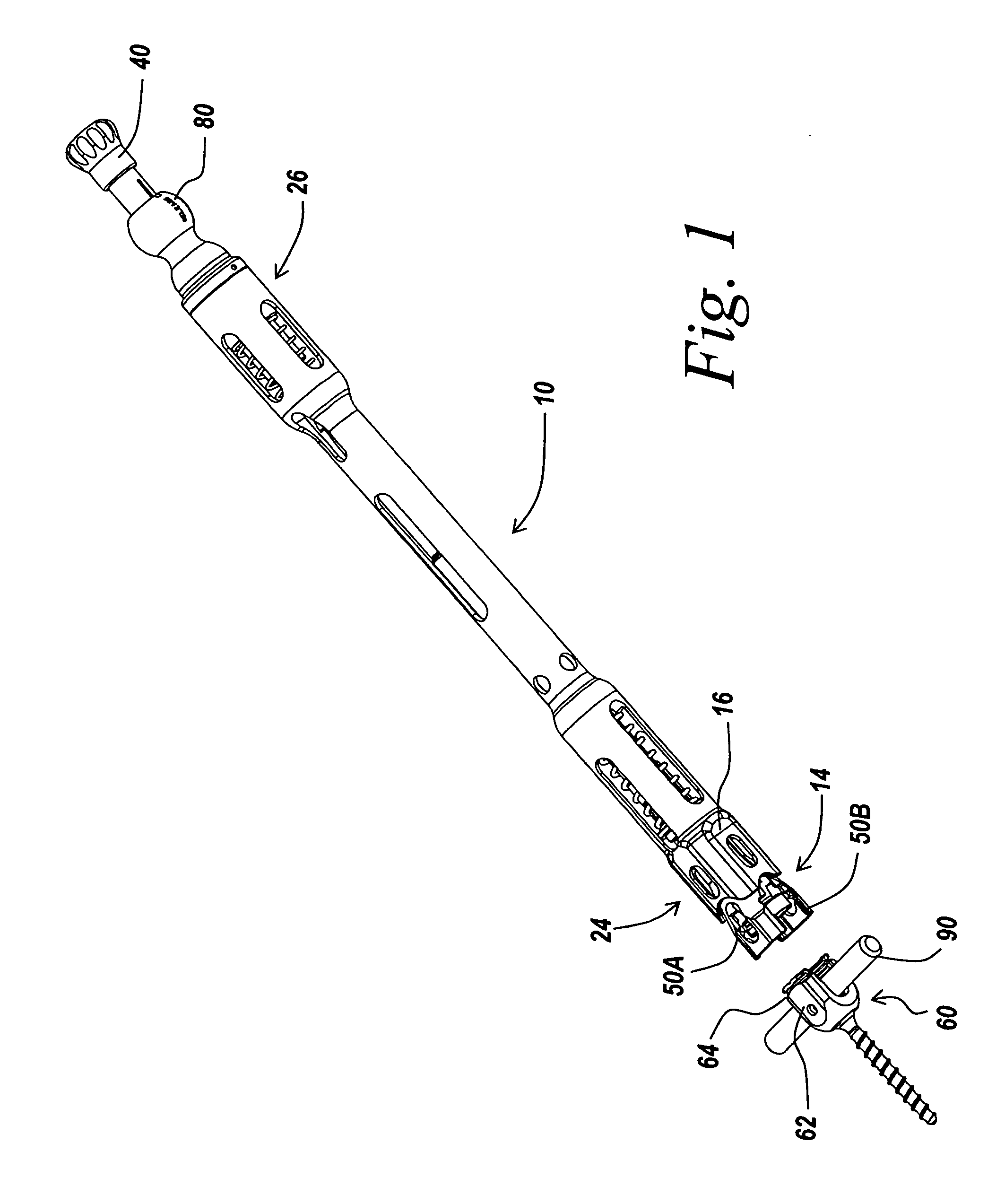
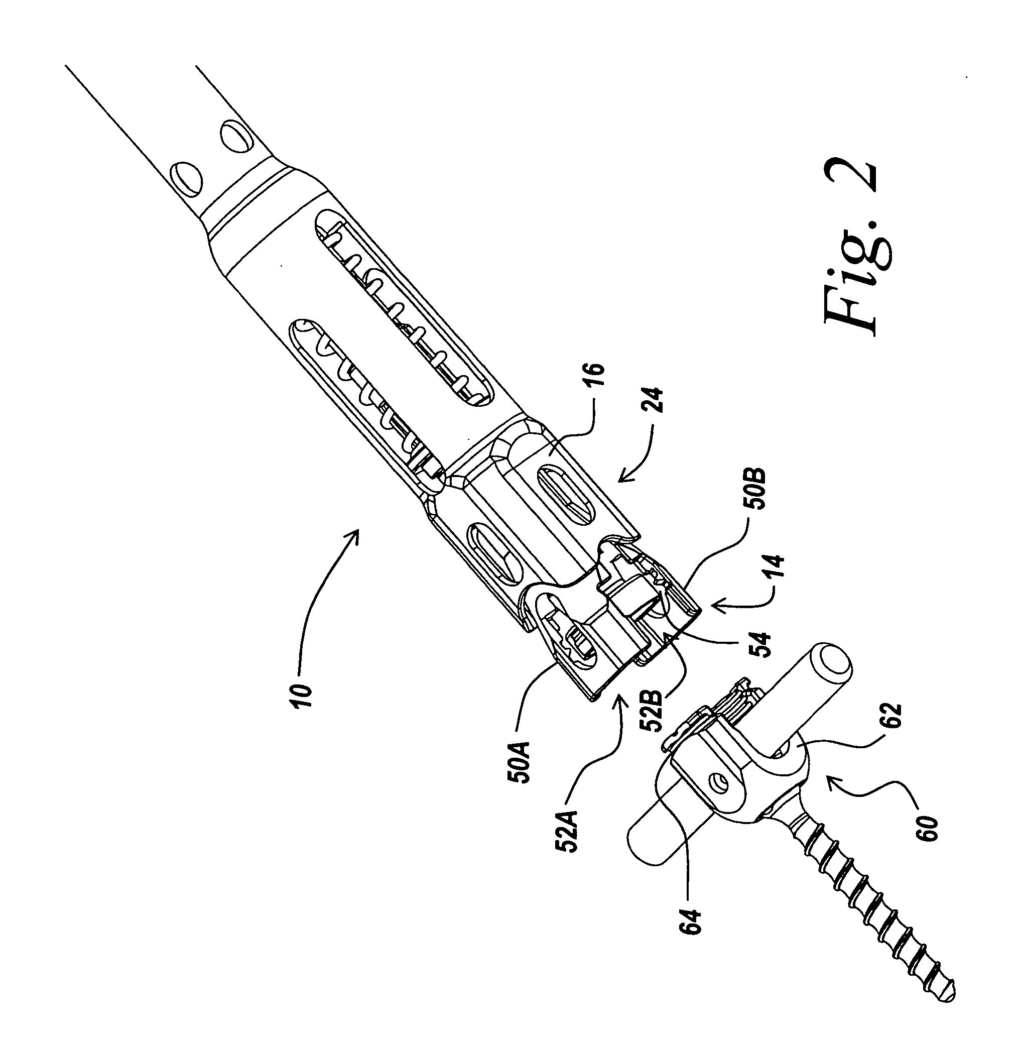
An instrument for manipulating a bone anchor and, in turn, a vertebral body to which the bone anchor is attached. The exemplary instrument includes an inner shaft, an anchor engagement mechanism, and an outer sleeve disposed about the inner shaft. The exemplary instrument may be employed to manipulate a bone anchor for implantation or adjustment. The exemplary instrument may also be use engage a bone anchor implanted in a vertebra and maneuver the bone anchor and the vertebra by manipulating the instrument. For example, the exemplary instrument may be employed to rotate the bone anchor and the vertebra relative to other vertebrae and thereby by correct the angular orientation of the vertebra. The instrument, when employed in the exemplary manner, thus may be used to effect segmental correction of the angular orientation of the vertebrae of the spine.

Description

FIELD OF THE INVENTION[0001]The present invention relates to a device and method for use during spinal correction surgery. More particularly, the present invention relates to a device and method for manipulating a bone anchor as well as vertebral body to which the bone anchor is attached.BACKGROUND OF THE INVENTION[0002]In spinal deformity surgical procedures, the curvature of the spine, for example, the coronal curvature and / or the sagittal curvature of the spine, can be corrected by the implantation of a construct of bone anchors (e.g., hooks or bone screws) and spinal fixation elements (e.g., rods or tethers). In addition to correcting the curvature of the spine, the angular relationship of one or more vertebrae relative to other vertebrae may also be corrected. Conventional surgical procedures for corrected the angular relationship of a vertebra involve rotating the spinal fixation element, for example, a spinal rod, connected to the vertebra by a bone anchor. In the case of con...

Claims


Application Information

Patent Timeline
IPC IPC(8): A61B17/58
CPCA61B17/7032A61B17/708A61B17/7038A61B17/7037
Inventor DONAHUE, JAMES R.ROSSER, TIMOTHY
Owner DEPUY SPINE INC (US)
Learn More