Single Joint Elevator Having Deployable Jaws

a single joint elevator and jaw technology, applied in the field of single joint elevators, can solve the problems of consuming a substantial amount of rig time, insufficient clearance around the casing segment for installing a conventional single joint, and difficulty in using conventional elevators on pipe segments that are not, so as to achieve the effect of increasing clearance and reducing clearan

Active Publication Date: 2008-07-24
FRANKS INT
View PDF40 Cites 51 Cited by
  • Summary
  • Abstract
  • Description
  • Claims
  • Application Information

AI Technical Summary

Benefits of technology

[0008]Each static jaw and each deployable jaw may comprise a pipe slip that is movable between an engaged position and a disengaged position. Movement of the slip toward the engaged position moves the slip radially inwardly toward the pipe within the slot to decrease the clearance between the pipe slip in the at least one static jaw and the generally opposed pipe slip in the at least one deployable jaw, and movement of the slip toward its disengaged position moves the slip radially outwardly away from the pipe within the slot to increase the clearance between the pipe slip in the at least one static jaw and the generally opposed pipe slip in the at least one deployable jaw. Each static jaw and each deployable jaw may comprise one or more grooves for slidably receiving tabs, keys, or guides for imposing a predetermined path for movement of the pipe slip within the jaw. For example, a pipe slip may have a pair of tabs, one protruding from each side of the slip, and each tab may be slidably received into a groove in the jaw for imposing upon the pipe slip a predetermined path of movement extending in the engaged direction for closing the pipe slips on the pipe received within the slot, and in the disengaged direction for retracting the pipe slips away from the pipe received within the slot. Each slip may comprise a pipe contact surface, such as a removable insert, that may comprise a textured surface adapted for gripping contact with the external wall of the pipe received into the slot.

Problems solved by technology

Conventional elevators are difficult to use on pipe segments that are not conveniently accessible.
Depending on the length of the pipe and the proximity of the floor or other rig structures, there may be insufficient clearance around the casing segment for installing a conventional single joint elevator, often requiring repositioning of the casing segment so that the single joint elevator can be installed around the casing segment.
Even if repositioning of each casing segment takes only a few seconds, delays for repeatedly repositioning casing segments in the V-door consumes a substantial amount of rig time.

Method used


Image

  • Single Joint Elevator Having Deployable Jaws
  • Single Joint Elevator Having Deployable Jaws
  • Single Joint Elevator Having Deployable Jaws

Examples


Embodiment Construction

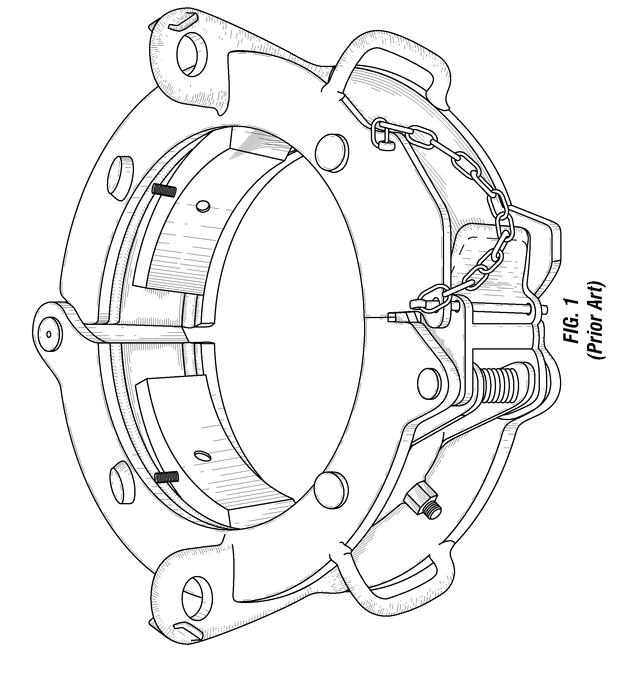
[0019]FIG. 1 is a perspective view of a prior art single joint elevator having a pair of opposing and hinged body halves for opening, receiving a pipe segment, and closing around a pipe segment (not shown) that is received within the opened body halves. These elevators are unsuitable for gripping pipe having integral connections, and they are unsuitable for gripping pipe with conventional connections at locations along the length of the pipe segment removed from the end of the segment. These elevators are often difficult to position on the pipe segment due to interference with the rig floor or other rig structures, as well as difficult to open and close, especially if the locking pin is in a bind.

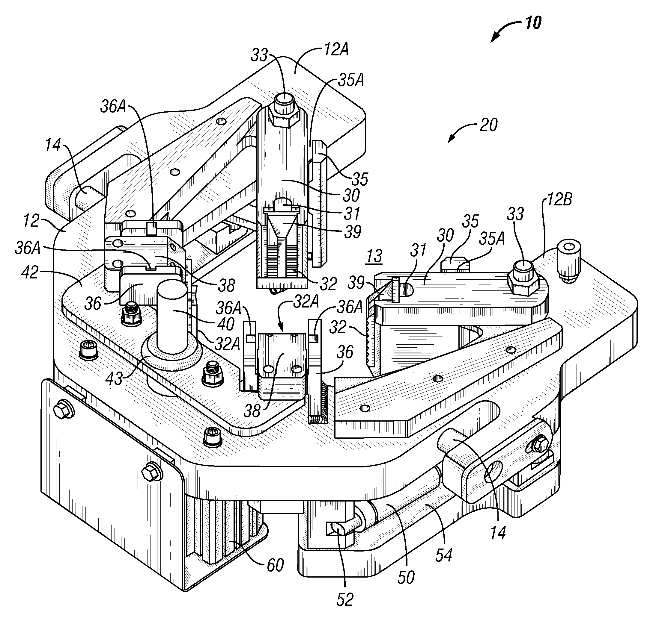
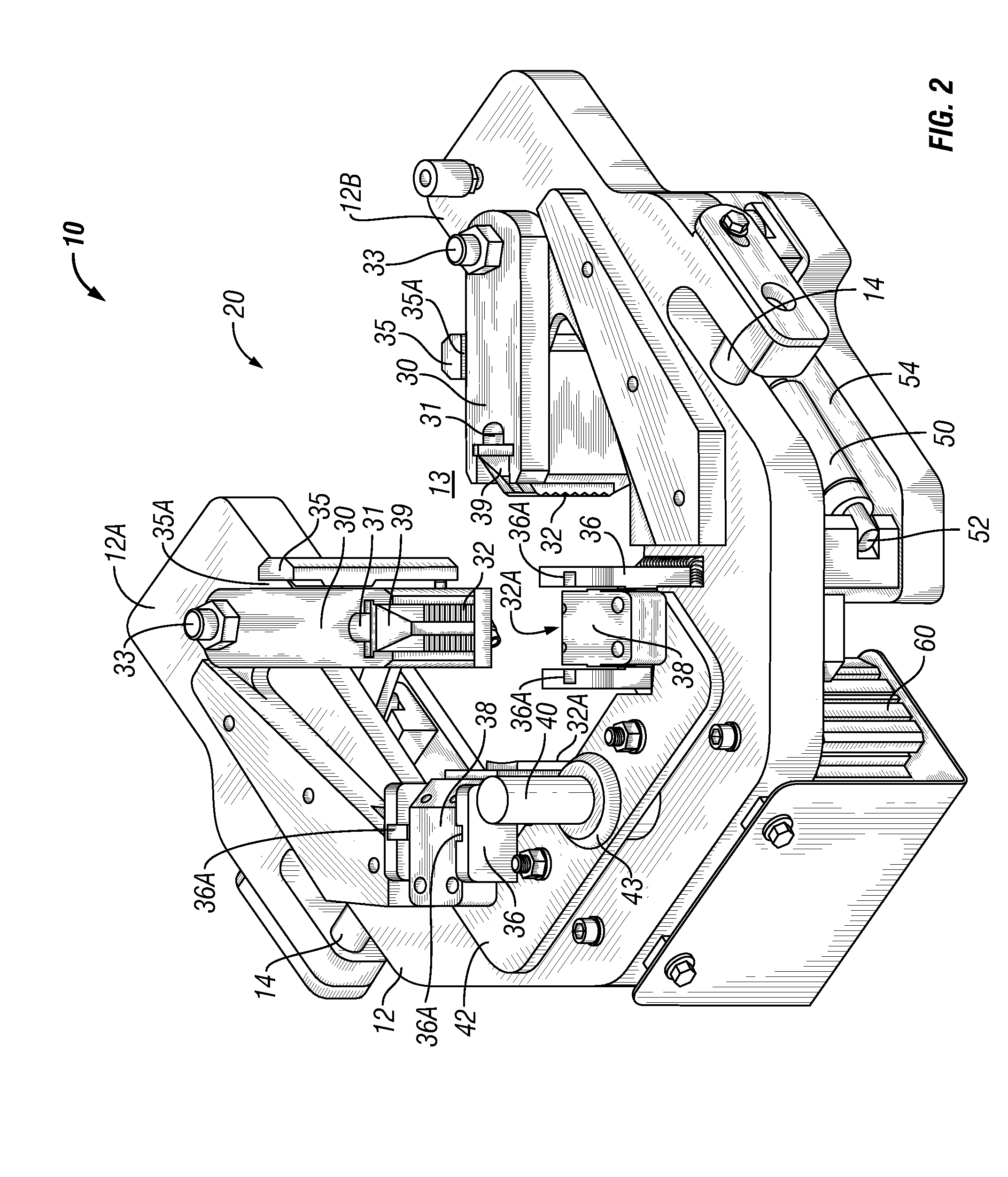
[0020]FIG. 2 is a perspective view of one embodiment of the single joint elevator 10 of the present invention showing a pair of generally opposed rotatably deployable jaws 30, both shown in their deployed positions to secure a pipe segment (not shown) within the slot 13 in the generally hor...


PUM


Abstract

The present invention provides an apparatus and a method for lifting a single joint of pipe. The single joint elevator of the present invention comprises, in one embodiment, a pair of deployable jaws cooperating with a pair of static jaws to secure a pipe within the slot of a generally horseshoe-shaped body. The deployable jaws of the single joint elevator of the present invention may be rotatably deployable or translatably deployable, or both. In one embodiment, each jaw, including the static jaws and the deployable jaws, comprises a pipe slip movably disposed within the jaw to secure a pipe segment within the slot and to self-tighten as the weight of the pipe segment secured within the single joint elevator is transferred to the slips and the jaws.

Description

FIELD OF THE INVENTION[0001]The present invention is directed to an apparatus and a method for securing a pipe segment or a stand of pipe to a cable, rope, line or other hoisting member to facilitate lifting of the pipe to an elevated position. The present invention is directed to an apparatus and a method for securely gripping and releasing a pipe segment or stand of pipe for use in drilling operations.BACKGROUND OF THE RELATED ART[0002]Wells are drilled into the earth's crust using a drilling rig. Pipe strings are lengthened by threadably coupling add-on pipe segments to the proximal end of the pipe string. The pipe string is generally suspended within the borehole using a rig floor-mounted spider as each new pipe segment or stand is coupled to the proximal end of the pipe string just above the spider. A single joint elevator is used to grip and secure the segment or stand to a hoist to lift the segment or stand into position for threadably coupling to the pipe string.[0003]For in...

Claims


Application Information

Patent Timeline
Patent Type & Authority Applications(United States)
IPC IPC(8): E21B19/06
CPCE21B19/07E21B19/12B66C1/44B66C15/06
Inventor BOULIGNY, VERNON JOSEPHARCENEAUX, SCOTT JOSEPH
Owner FRANKS INT
Why Eureka
Try Eureka