Ignition device having an induction welded and laser weld reinforced firing tip and method of construction

a firing tip and laser welding technology, applied in the manufacture of sparking plugs, sparking plugs, electrical appliances, etc., can solve the problems of increased manufacturing costs, limited number of firing tip materials available for use, and potential drawbacks of each type of firing tip

Active Publication Date: 2008-07-24
FEDERAL MOGUL WORLD WIDE LLC
View PDF36 Cites 17 Cited by
  • Summary
  • Abstract
  • Description
  • Claims
  • Application Information

AI Technical Summary

Benefits of technology

[0012]An ignition device for an internal combustion engine constructed in accordance with the invention includes a housing having an opening and an insulator secured within the housing. The insulator has an end exposed through the opening in the housing. A center electrode is mounted within the insulator and has an outer surface extending to an end beyond the insulator. A ground electrode extends from the housing with a portion of the ground electrode being located opposite the end of the center electrode to define a spark gap therebetween. The center electrode has a precious-metal firing tip initially bonded to its end by a resistance weld joint. A continuous bead of overlapping laser weld pools extends about an outer periphery of the firing tip to further bond the firing tip to the center electrode. The weld pools form at least a portion of a rounded shoulder that extends from the firing tip to the outer surface of the center electrode.
[0013]Another aspect of the invention includes an electrode assembly for an ignition device. The electrode assembly has an electrode body with an outer surface and a firing tip with a lower surface and an outer periphery. A resistance weld joint bonds the firing tip lower surface to the electrode body so that the lower surface is embedded a first distance beneath the outer surface. A continuous bead of overlapping laser weld pools is formed over the firing tip outer periphery, with the laser weld pools extending a second distance beneath the electrode body outer surface with the second distance being greater than the first distance.
[0014]Yet another aspect of the invention includes a method of constructing an ignition device for an internal combustion engine. The method includes providing a housing and securing an insulator within the housing so that an end of the insulator is exposed through an opening in the housing. Then, mounting a center electrode body having an outer surface within the insulator with a firing tip region of the center electrode body extending beyond the insulator. Then, extending a ground electrode body having an outer surface from the housing with a firing tip region of the ground electrode body being located opposite the firing tip region of the center electrode body to define a spark gap therebetween. Further, providing at least one preformed piece of firing tip material formed from noble metal. Further yet, resistance welding the at least one piece of firing tip material to at least one of the center electrode body or ground electrode body to at least partially form a firing tip, with the resistance weld joint defining a lower surface of the firing tip that is a first distance beneath the outer surface. Then, laser welding a continuous bead of overlapping laser weld pools over an outer periphery of the firing tip with the weld pools extending a second distance beneath the outer surface, wherein the second distance is greater than the first distance.
[0015]Another aspect of the invention includes a method of constructing an ignition device. The method includes providing an electrode body having an outer surface and a preformed piece of noble metal firing tip material. Then, resistance welding the firing tip material to the body to at least partially form a firing tip and defining a lower surface of the firing tip a first distance beneath the outer surface. Further, laser welding a continuous bead of overlapping laser weld pools over an outer periphery of the firing tip so that the weld pools extend a second distance beneath the outer surface, wherein the second distance is greater than the first distance.

Problems solved by technology

Of all the known electrode constructions having a precious metal firing tip, including those discussed above, each comes with potential drawbacks.
Some of the possible drawbacks include, increased costs in manufacture, a limited number of types of firing tip materials available for use, or a combination thereof.

Method used


Image

  • Ignition device having an induction welded and laser weld reinforced firing tip and method of construction
  • Ignition device having an induction welded and laser weld reinforced firing tip and method of construction
  • Ignition device having an induction welded and laser weld reinforced firing tip and method of construction

Examples


Embodiment Construction

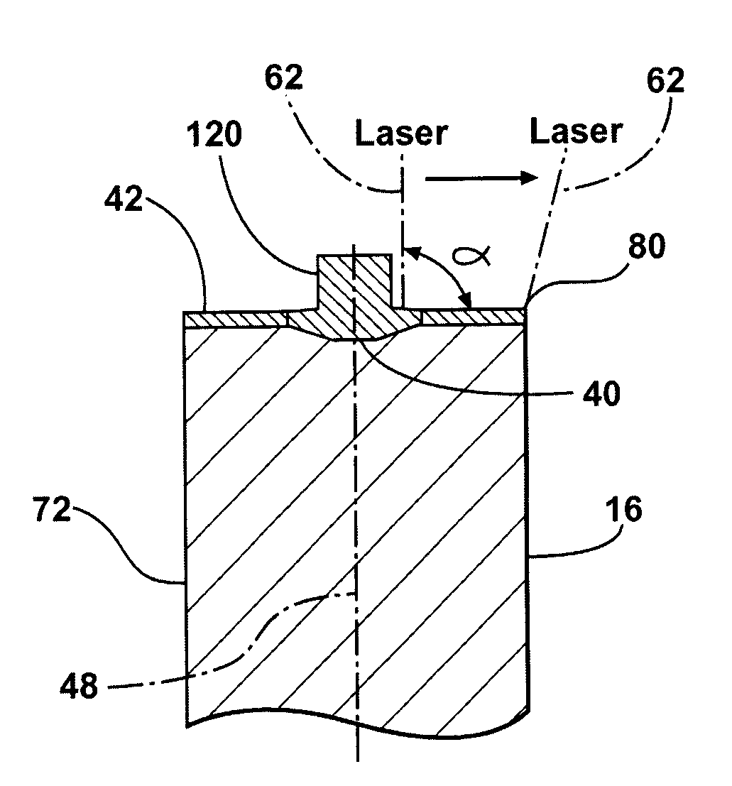
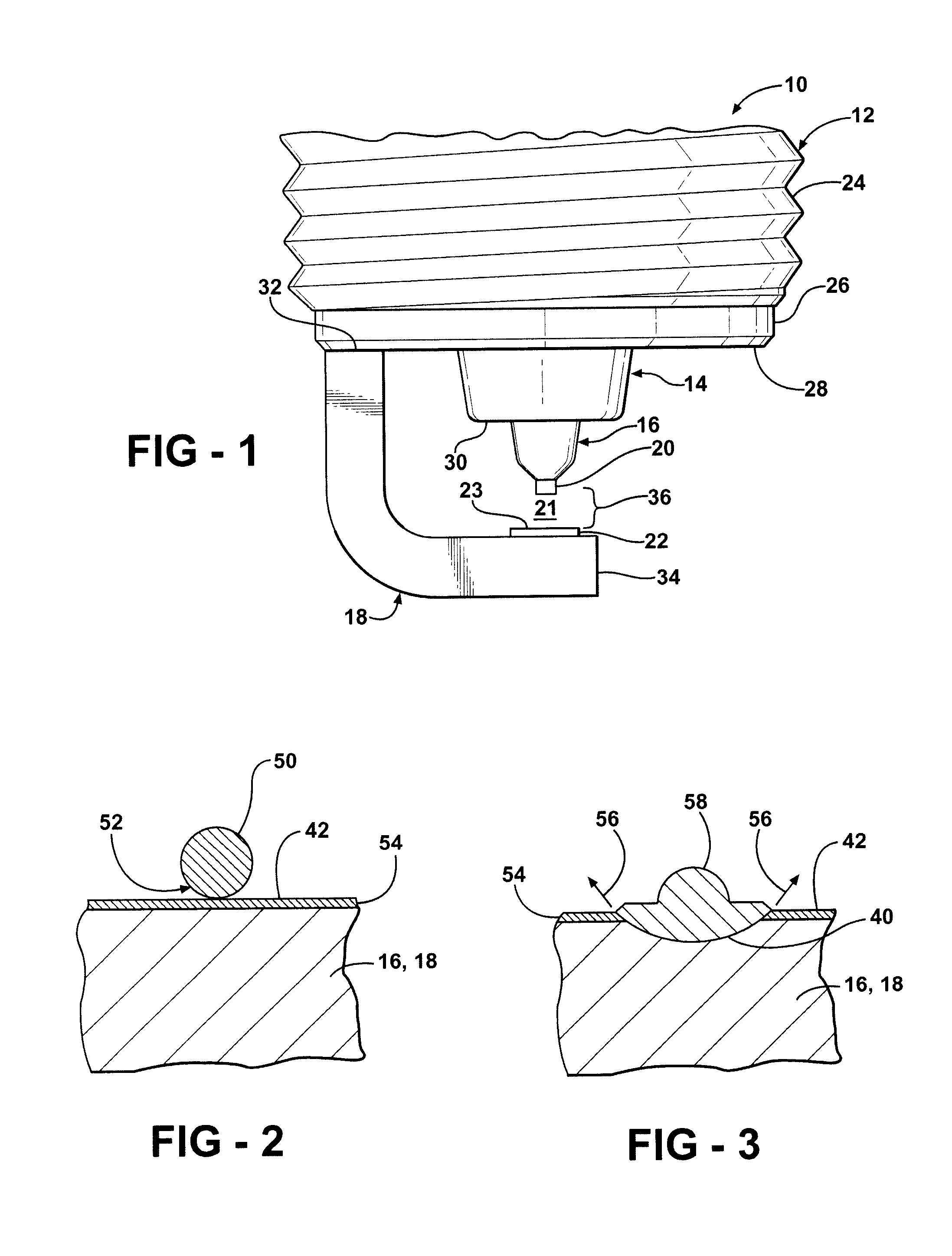
[0034]Referring in more detail to the drawings, FIG. 1 shows a firing end of a spark plug 10 constructed according to one presently preferred method of construction of the invention. The sparkplug 10 includes a metal casing or housing 12, an insulator 14 secured within the housing 12, a center electrode 16, a ground electrode 18, and a pair of firing tips 20, 22 located opposite each other on the center and ground electrodes 16, 18, respectively. The housing 12 can be constructed in a conventional manner as a metallic shell and can include standard threads 24 and an annular lower end 26 from which the ground electrode 18 extends, such as by being welded or otherwise attached thereto. Similarly, all other components of the sparkplug 10 (including those not shown) can be constructed using known techniques and materials, with exception to the center and / or ground electrodes 16, 18 which have firing tips 20, 22 constructed in accordance with the present invention.

[0035]As is known, the ...


PUM


Abstract

An ignition device for an internal combustion engine and method of construction therefore includes a housing with an insulator secured therein. A center electrode is mounted within the insulator. A ground electrode extends from the housing with a portion of the ground electrode defining a spark gap across from the center electrode. The center electrode has a firing tip, wherein a resistance weld joint initially bonds the firing tip to the center electrode and a continuous bead of overlapping first weld pools formed substantially from the material of the firing tip further bonds the firing tip to the electrode. A continuous bead of overlapping second weld pools formed radially outwardly from the first weld pools forms a rounded shoulder surface extending from the first weld pools to an outer surface of the center electrode.

Description

CROSS-REFERENCE TO COPENDING APPLICATION[0001]This application is a continuation-in-part of U.S. patent application Ser. No. 11 / 624,272, filed on Jan. 18, 2007, which is incorporated herein by reference in its entirety.BACKGROUND OF THE INVENTION[0002]1. Technical Field[0003]This invention relates generally to spark plugs and other ignition devices, and more particularly to electrodes having noble metal firing tips and to methods of construction thereof.[0004]2. Related Art[0005]Within the field of spark plugs, there exists a continuing need to improve the erosion resistance and reduce the breakdown voltage between the spark plug's center and ground electrodes. Various designs have been proposed using noble metal electrodes or, more commonly, noble metal firing tips applied to standard metal electrodes. Typically, the firing tip is formed as a pad or rivet which is then welded onto the end of the electrode.[0006]In constructing firing tips with noble, also referred to as precious me...

Claims


Application Information

Patent Timeline
Patent Type & Authority Applications(United States)
IPC IPC(8): H01T1/22H01T13/39H01T21/02
CPCH01T13/32H01T21/02H01T13/39
Inventor KOWALSKI, KEVIN JAYTINWELL, PAUL
Owner FEDERAL MOGUL WORLD WIDE LLC
Why Eureka
Try Eureka