Ophthalmic measurement apparatus

a technology of ophthalmic measurement and measuring device, which is applied in the field of ophthalmic measurement device, can solve problems such as disagreement between obtained objective values

Active Publication Date: 2008-07-24
NIDEK CO LTD
View PDF5 Cites 12 Cited by
  • Summary
  • Abstract
  • Description
  • Claims
  • Application Information

AI Technical Summary

Benefits of technology

[0007]To achieve the objects and in accordance with the purpose of the present invention, an ophthalmic measurement apparatus has a measurement optical system for projecting a measurement target onto a fundus of an examinee's eye and detecting an image of the measurement target reflected from the fundus by using a photoelectric element so as to obtain measurement data on eye refractive power distribution or wavefront aberration of the examinee's eye, a photographing optical system for photographing an anterior-segment including a pupil of the examinee's eye by using an image-pickup element, detection means which detects a size of a pupil area by processing the photographed image of the anterior-segment, and correction data calculating means which obtains a spherical power, an astigmatic power, and an astigmatic axial angle based on the measurement data within a given area which is smaller than the pupil area when the detected size of the pupil area is larger than a reference size, and obtains the spherical power, the astigmatic power, and the astigmatic axial angle based on the measurement data within the pupil area when the detected size of the pupil area is smaller than the reference size.
[0008]In another aspect of t

Problems solved by technology

However, a certain disagreement is developed between the obtained objective values and information on optica

Method used


Image

  • Ophthalmic measurement apparatus
  • Ophthalmic measurement apparatus
  • Ophthalmic measurement apparatus

Examples


Embodiment Construction

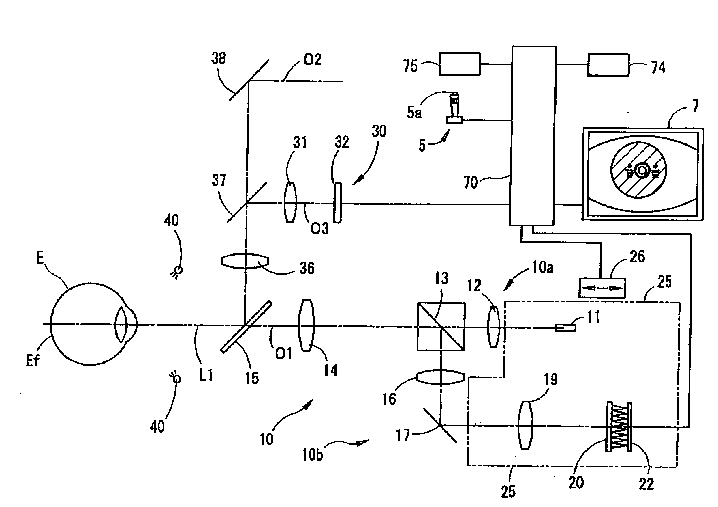
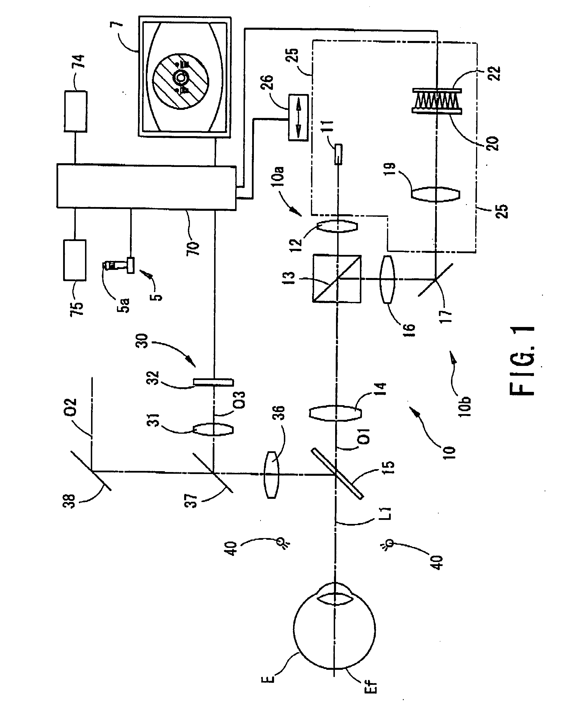
[0013]A detailed description of one preferred embodiment of an ophthalmic measurement apparatus embodied by the present invention is provided below with reference to the accompanying drawings. FIG. 1 is a view showing an optical system and a control system of the ophthalmic measurement apparatus according to the preferred embodiment of the present invention. A dichroic mirror 15 is placed in front of a patient's eye E. On a transmission optical path O1 of the dichroic mirror 15, a wavefront aberration measurement optical system 10 for measuring wavefront aberration of the patient's eye E is placed. The measurement optical system 10 includes a projection optical system 10a for projecting measurement light in a spot shape (a measurement target) which is emitted from a measurement light source 11 onto a fundus Ef, and a photo-receiving optical system 10b for dividing the measurement light reflected from the fundus Ef and emitted from the patient's eye E into a plurality of light bundle...


PUM


Abstract

An ophthalmic measurement apparatus capable of outputting correction data (objective values) for a patient's eye as approximate as possible to subjective values includes an optical system for projecting a measurement target onto a fundus and detecting an image of the target reflected therefrom using a photoelectric element so as to obtain measurement data on eye refractive power distribution or wavefront aberration, an optical system for photographing an anterior-segment including a pupil using an image-pickup element, a device which detects a size of a pupil area by image processing, and a device which obtains a spherical power, an astigmatic power, and an astigmatic axial angle based on the data within a given area smaller than the pupil area when the detected size is larger than a reference size, and obtains the three values based on the data within the pupil area when the detected size is smaller than the reference size.

Description

BACKGROUND OF THE INVENTION[0001]1. Field of the Invention[0002]The present invention relates to an ophthalmic measurement apparatus which measures eye refractive power distribution or wavefront aberration of a patient's eye.[0003]2. Description of Related Art[0004]Conventionally, there is known an apparatus which projects light in a spot shape (a measurement target) onto a fundus of a patient's eye (an examinee's eye) and detects information on wavefront of the light reflected from the fundus by using a wavefront sensor (photoelectric element) so as to measure wavefront aberration (especially, higher-order aberration) of the patient's eye (see U.S. Pat. No. 6,234,978 corresponding to Japanese Patent Application Unexamined Publication No. Hei 10-216092). In addition, there is known an ophthalmic apparatus which projects slit light onto a fundus of a patient's eye and detects the light reflected from the fundus by using a photoelectric element so as to measure the wavefront aberratio...

Claims


Application Information

Patent Timeline
IPC IPC(8): A61B3/14
CPCA61B3/14A61B3/1015
Inventor SHIMIZU, KAZUNARIFUJIEDA, MASANAO
Owner NIDEK CO LTD
Why Eureka
Try Eureka