
Projection Display with Holographic Screen

Inactive Publication Date: 2008-07-24
EMISCAPE
View PDF31 Cites 56 Cited by
  • Summary
  • Abstract
  • Description
  • Claims
  • Application Information

AI Technical Summary

Problems solved by technology

However, advertisements on the side of a building cover up what otherwise would be space for windows in the building.

Method used


Image

  • Projection Display with Holographic Screen
  • Projection Display with Holographic Screen
  • Projection Display with Holographic Screen

Examples


Embodiment Construction

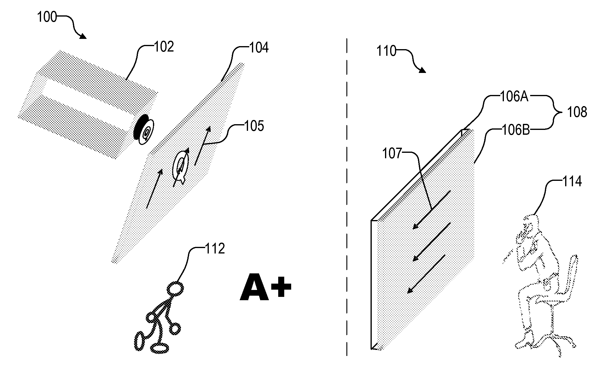
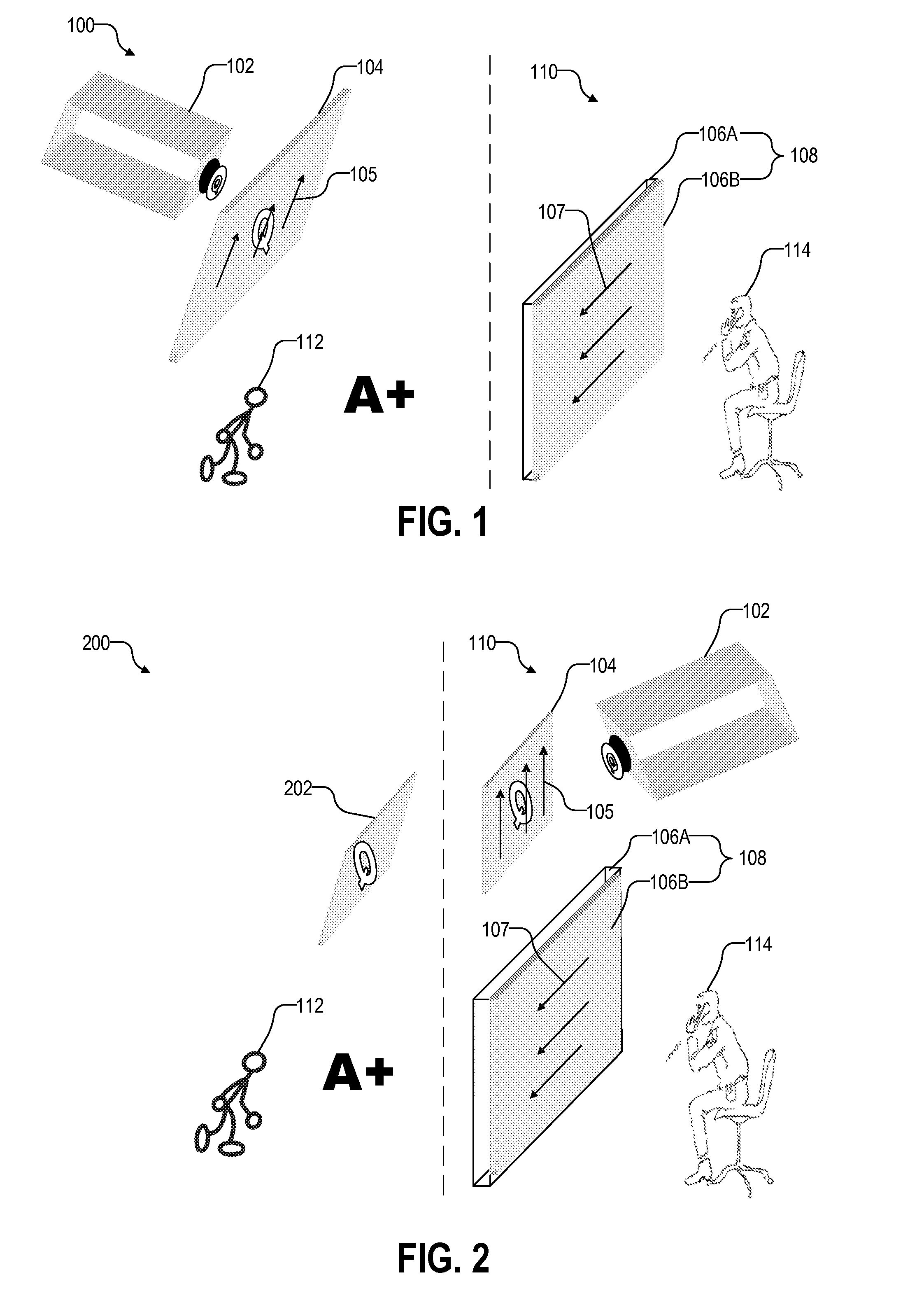
[0016]FIG. 1 illustrates a polarized front-projection system 100 in one embodiment of the invention. System 100 includes a projector 102 that generates an image “Q.” Projector 102 may be a liquid crystal display (LCD) projector, a digital light processing (DLP) projector, a laser projector, a slide projector, or any device capable of projecting an image. Depending on the application, image Q may be a still advertisement, a slideshow of still advertisements, a video advertisement, or virtually any image.

[0017]Image Q propagates through a polarizer 104 having a polarization direction 105. In one embodiment, polarizer 104 is a polarizing film near the lens of projector 102. After passing through polarizer 104, image Q only has light aligned along polarization direction 105. Alternatively, projector 102 can generate an image Q that is already polarized along direction 105.

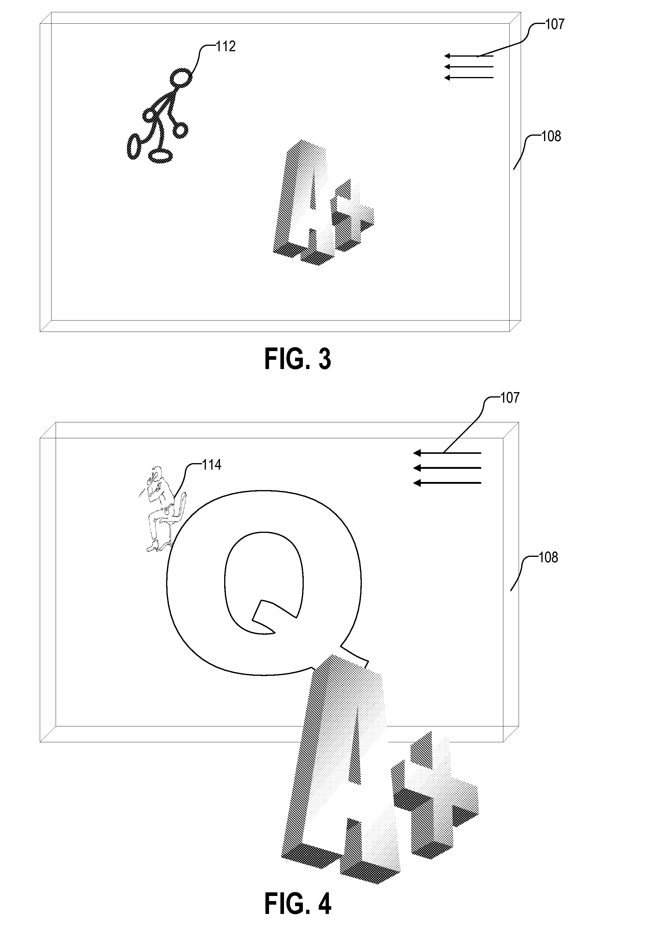
[0018]Image Q then propagates onto a semi-permeable screen 108. Semi-permeable screen 108 includes a display portion...


PUM


Abstract

A projection display system includes (1) a polarizer, (2) a holographic screen with holographic optical elements having the properties of a display portion and a polarizing portion, and (3) a projector for projecting an image through the polarizer and onto the holographic screen. The polarizing portion of the holographic screen has a different polarization direction from the polarizer such that the image is visible from a first side of the holographic screen and invisible from a second side of the holographic screen.

Description

CROSS REFERENCE TO RELATED APPLICATION[0001]This application is related to U.S. patent application Ser. No. 11 / 109,543, entitled “Polarized Projection Display,” filed on Apr. 18, 2005, and U.S. patent application Ser. No. 11 / 367,687, entitled “One-Way Transparent Display Systems,” filed on Mar. 3, 2006, which are incorporated herein by reference.FIELD OF INVENTION[0002]This invention relates to displays, and specifically to transparent displays with an image that is visible from one side of the display but not the other.DESCRIPTION OF RELATED ART[0003]Generally speaking, advertising is the paid promotion of goods, services, companies and ideas by an identified sponsor. Advertisements on the sides of buildings were common in the early-20th century U.S. One modern example is the NASDAQ sign at the NASDAQ Market Site at 4 Times Square on 43rd Street. Unveiled in January 2000, it cost $37 million to build. The sign is 120 feet high and is the largest LED display in the world. NASDAQ pay...

Claims


Application Information

Patent Timeline
Patent Type & Authority Applications(United States)
IPC IPC(8): G03B31/00G03B21/14
CPCG02B5/32G02B27/2278G02B27/283G09F19/22G03B21/604G03H2250/41G09F19/18G03B21/10G02B30/52
Inventor QUACH, CANG V.GLASER, WILLIAM
Owner EMISCAPE
Learn More