Overhead cable termination arrangement

a technology of termination arrangement and overhead cable, which is applied in the direction of optics, instruments, optical light guides, etc., can solve the problem of limited space to accommodate the increasing demand for telecommunication services

Active Publication Date: 2008-07-24
COMMSCOPE TECH LLC
View PDF14 Cites 16 Cited by
  • Summary
  • Abstract
  • Description
  • Claims
  • Application Information

AI Technical Summary

Benefits of technology

[0004]The present disclosure relates to an overhead cable management system including a cable termination device that mounts to an overhead cable pathway structure. The overhead cable pathway structure can include, for example, a U-shaped trough or a ladder-type structure. The overhead arrangement of the cable termination device allots more space on equipment racks or in equipment cabinets for telecommunication equipment.

Problems solved by technology

Space to accommodate the increasing demand for telecommunication services is limited.

Method used


Image

  • Overhead cable termination arrangement
  • Overhead cable termination arrangement
  • Overhead cable termination arrangement

Examples


Embodiment Construction

[0016]Reference will now be made in detail to exemplary aspects of the present disclosure that are illustrated in the accompanying drawings. Wherever possible, the same reference numbers will be used throughout the drawings to refer to the same or like parts.

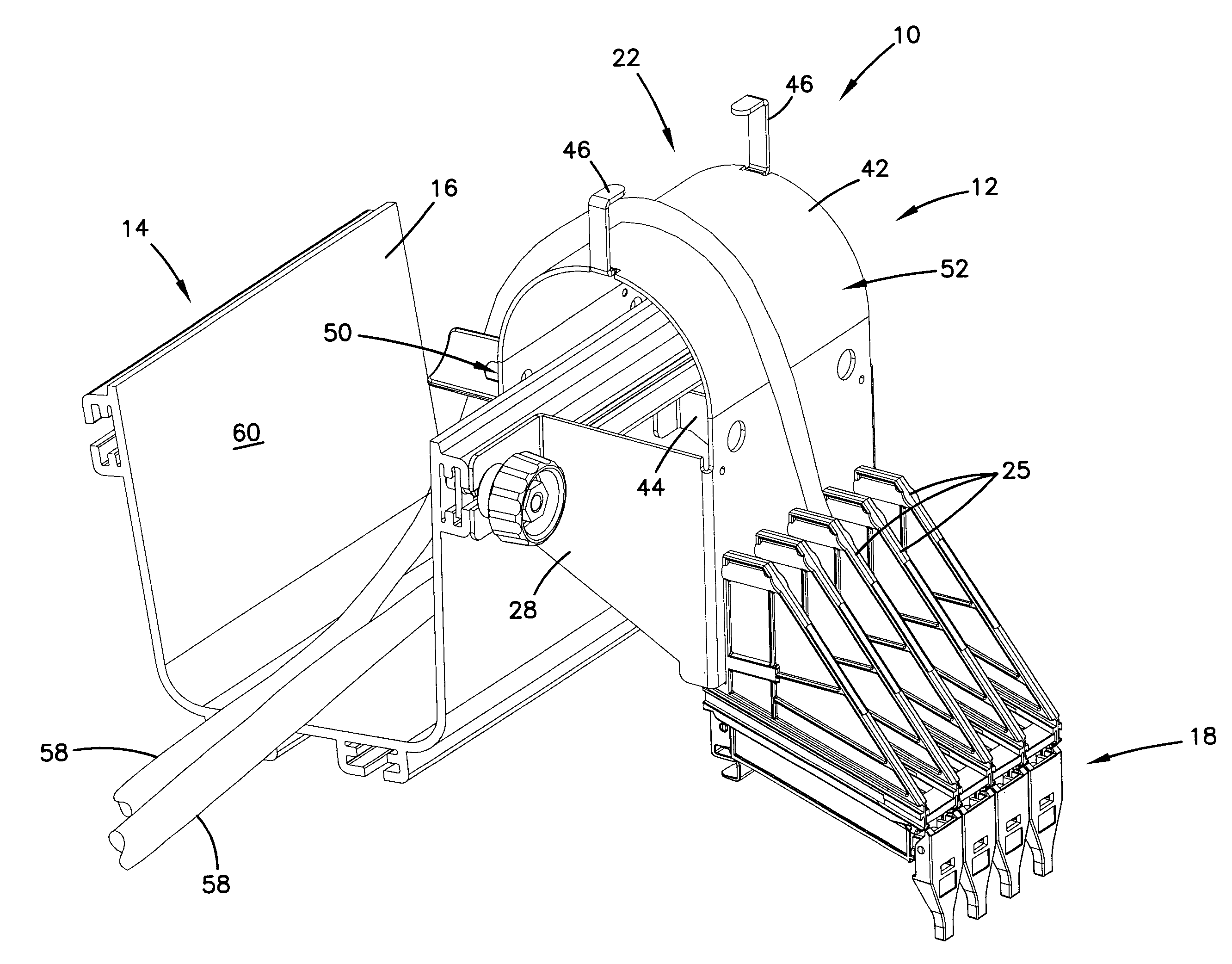
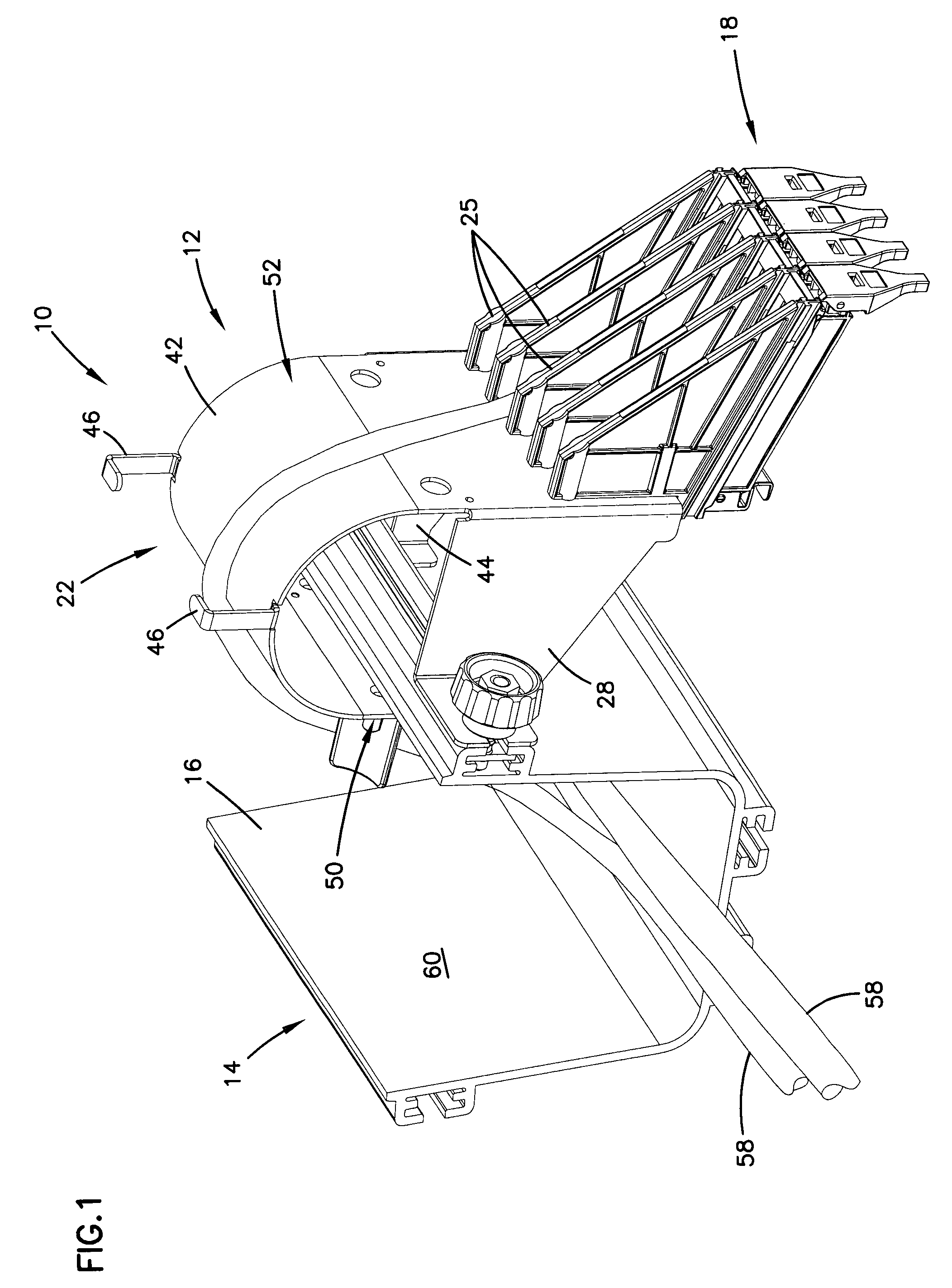
[0017]FIG. 1 illustrates one embodiment of an overhead cable management system 10 in accordance with the principles disclosed. The overhead cable management system 10 is designed to manage and organize cables and related components to increase capacity in limited telecommunication facility space. The overhead cable management system 10 of the present disclosure generally includes a cable termination panel or device 12 that mounts to an overhead cable pathway structure 14.

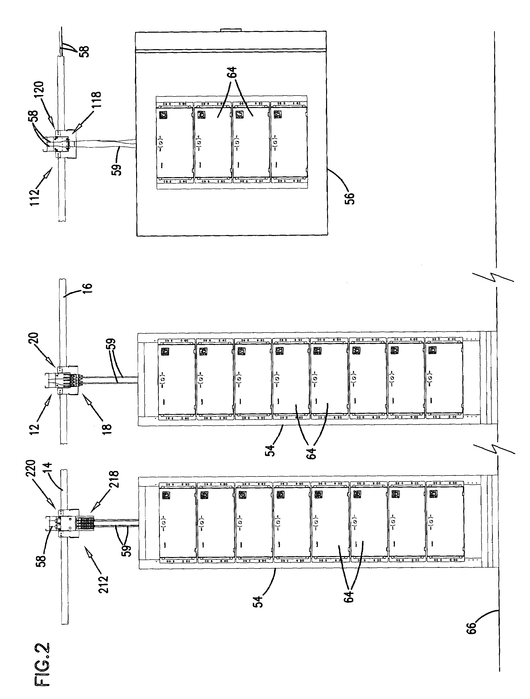
[0018]Referring to FIG. 2, in telecommunication facilities, such as data centers or central offices, for example, overhead cable pathway structures 14 are hung above racks (e.g. 54), cabinets (e.g., 56), and / or other equipment enclosures or framework. The overhe...


PUM

PropertyMeasurementUnit
cable pathway structureaaaaaaaaaa
structuresaaaaaaaaaa
heightaaaaaaaaaa

Abstract

A system including an overhead cable pathway structure and an adapter panel or cable termination device that mounts overhead to the cable pathway structure. The cable termination device including a plurality of adapters and a cable pathway exit having a curved surface that guides cables exiting from the overhead cable pathway structure to the adapters.

Description

FIELD OF THE INVENTION[0001]This disclosure relates to methods and devices for use in the telecommunications industry. More specifically, this disclosure relates to methods and devices for use in managing and organizing telecommunications cables and cable termination components.BACKGROUND OF THE INVENTION[0002]In the telecommunications industry, effective management and organization of cables and associate cable termination components is necessary in light of the massive cabling schematics involved in providing telecommunication services. Telecommunication facilities, such as data centers or central offices, for example, often have rows of equipment racks and / or equipment cabinets interconnected to cables routed overhead. The cabling schematics of such facilities involve dropping cables down from overhead troughs or ladders, for example, and terminating the cables to termination panels mounted on the racks or in the cabinets.[0003]Space to accommodate the increasing demand for telec...

Claims


Application Information

Patent Timeline
Patent Type & Authority Applications(United States)
IPC IPC(8): G02B6/48
CPCG02B6/4459Y10T29/49826H02G3/0608
Inventor COBURN, HUTCHSMRHA, MARKSJODIN, CHADFLEMING, CRAIG
Owner COMMSCOPE TECH LLC
Why Eureka
Try Eureka