Laryngoscope with a Movable Image-Capturing Unit

Inactive Publication Date: 2008-07-24
CHEN TIEN SHENG
View PDF12 Cites 33 Cited by
  • Summary
  • Abstract
  • Description
  • Claims
  • Application Information

AI Technical Summary

Benefits of technology

[0008]It is therefore an object of the present invention to provide a laryngoscope having a movabl

Problems solved by technology

However, there is great variation among patients' anatomy, and there are many cases in which the early laryngoscope 10P cannot be used satisfactorily.
However, said improvements are still unable to fully address users' needs.
First, the pushing mechanism used in th

Method used


Image

  • Laryngoscope with a Movable Image-Capturing Unit
  • Laryngoscope with a Movable Image-Capturing Unit
  • Laryngoscope with a Movable Image-Capturing Unit

Examples


Embodiment Construction

[0027]To further clarify the features of the present invention, several preferred embodiments are disclosed hereafter

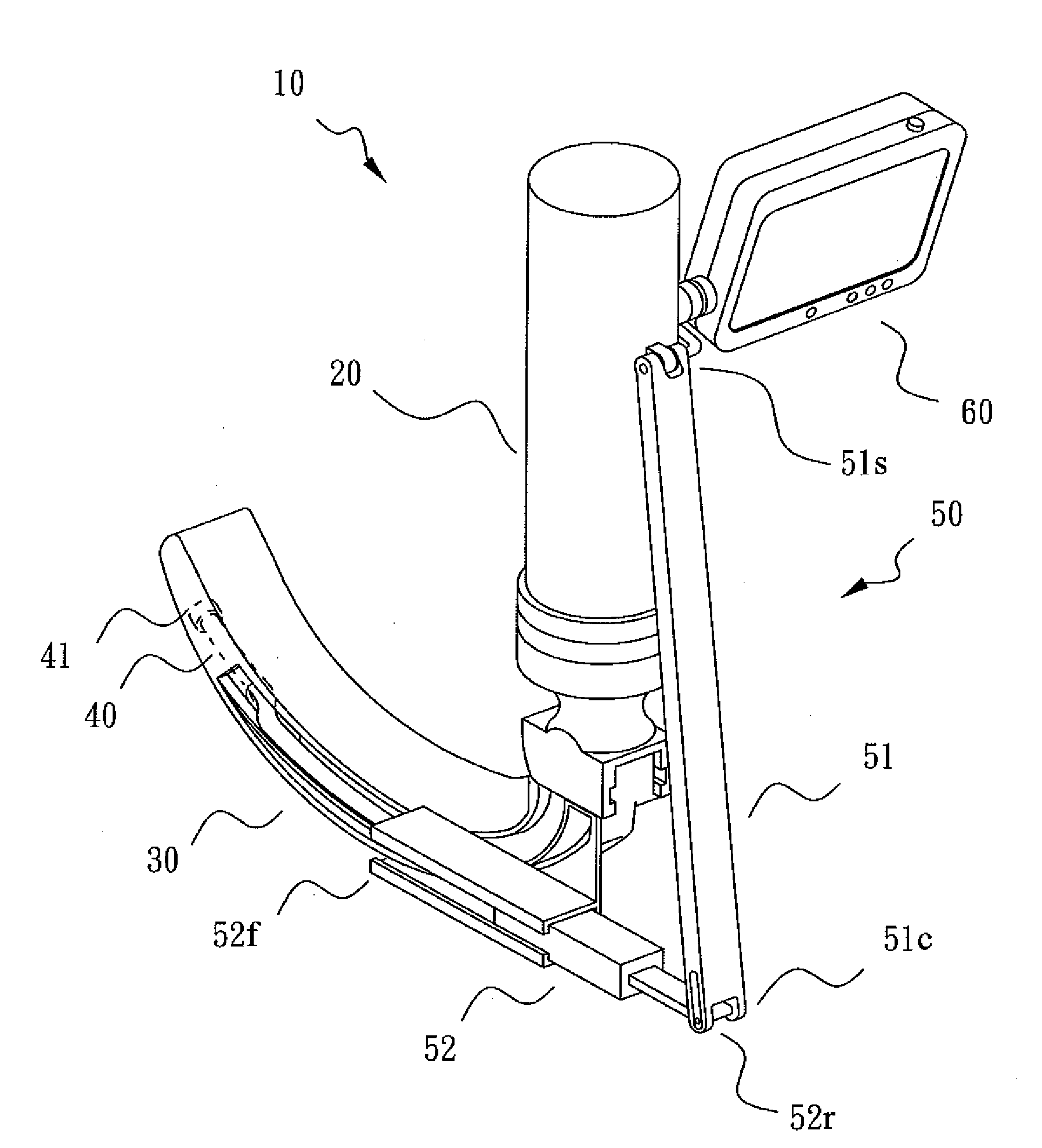
[0028]Please refer to FIG. 3 for a three-dimensional diagram of a laryngoscope 10 of the present invention. As shown, the laryngoscope 10 mainly comprises a handgrip 20, a blade 30, and an image-capturing unit 40 for capturing an image; the blade 30 is connected to the handgrip 20, and the image-capturing unit 40 is movably secured on the blade 30. In use, users may adjust the view of the laryngoscope 10 by pushing or pulling the image-capturing unit 40.

[0029]In addition, to enable users to move the image-capturing unit 40 more conveniently, the laryngoscope of the present invention 10 may further comprise an adjustment piece 50; said adjustment piece 50 has a pushing part 52 and a supporting part 51, and said pushing part 52 has a front end 52f and a rear end 52r; said supporting part 51 has a fixed end 51s connected to the handgrip 20 and a joint end 51c pivotally m...


PUM


Abstract

What is disclosed is a laryngoscope comprising a handgrip, a blade, and an image-capturing unit for capturing an image. The blade is connected to the handgrip, and the image-capturing unit is movably secured on the blade; in use, users may adjust the view of the laryngoscope by moving the image-capturing unit.

Description

BACKGROUND OF THE INVENTION[0001]1. Field of the Invention[0002]The present invention relates to a laryngoscope; more particularly, the present invention relates to a laryngoscope with a movable image-capturing unit.[0003]2. Description of the Related Art[0004]Endotracheal intubation is a critical means for maintaining the breathing function of a patient under general anaesthesia. In most cases, to prevent the occurrence of hypoxia, anaesthetists have to complete the intubation by inserting an endotracheal tube into patients' trachea in a very short period of time to provide oxygen thereinto promptly. Therefore, it is extremely important for anaesthetists to perform the intubation efficiently.[0005]To intubate quickly, most anaesthetists take advantage of a laryngoscope as a means to observe the condition of a patient's upper airway. Please refer to FIG. 1. An early laryngoscope 10P mainly consists of a handgrip 20 and a blade 30. It is generally used on a patient lying face up with...

Claims


Application Information

Patent Timeline
IPC IPC(8): A61B1/267
CPCA61B1/0676A61B1/05A61B1/00052A61B1/267
Inventor CHEN, TIEN-SHENGYUAN, HUI-BIH
Owner CHEN TIEN SHENG
Why Eureka
Try Eureka