Design method of combination instrument, combination instrument and vehicle

A technology of combination instrument and design method, which is applied to the arrangement of accessories on the instrument panel and other directions, can solve the problems of limited application scope, high cost, affecting the driver's reading of the display information of the combination instrument, etc., so as to improve the user experience and avoid The effect of user complaints

Inactive Publication Date: 2015-04-01
TIANJIN BOXIN AUTOMOBILE PARTS
View PDF7 Cites 15 Cited by
  • Summary
  • Abstract
  • Description
  • Claims
  • Application Information

AI Technical Summary

Problems solved by technology

When the driver is in the driving position, since the combination instrument cover is similar to a concave lens, according to the principle of reflection, the driver’s body parts or clothes will appear on the mask, especially some bright clothes, which will affect the driver’s understanding of the information displayed on the combination instrument. Reading, which will have a bad influence on the quality of the product
[0003] At present, some models use new materials to reduce the degree of mask imaging to achieve the purpose of reducing the impact. However, only some luxury models use new materials to reduce the impact of instrument mask imaging. Due to the high cost, and the impact of suppliers' technical capabilities and supply capabilities, many low-end and mid-end models have not been adopted, and the scope of application is limited.

Method used


Image

  • Design method of combination instrument, combination instrument and vehicle
  • Design method of combination instrument, combination instrument and vehicle
  • Design method of combination instrument, combination instrument and vehicle

Examples


Embodiment Construction

[0031] It should be noted that, in the case of no conflict, the embodiments of the present invention and the features in the embodiments can be combined with each other.

[0032] The present invention will be described in detail below with reference to the accompanying drawings and examples.

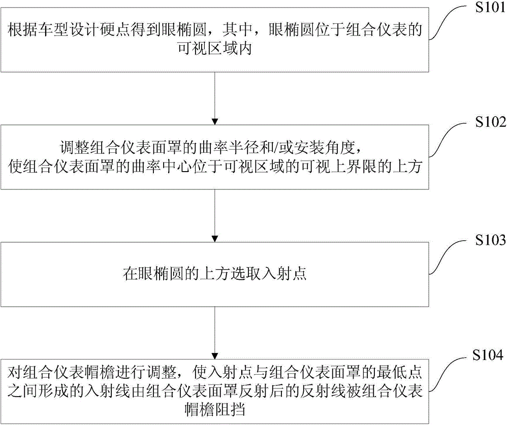
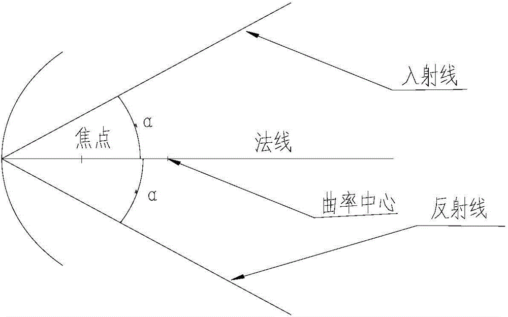
[0033] figure 1 is a flowchart of a design method for a combination meter according to an embodiment of the present invention. Such as figure 1 shown, combined with figure 2 , according to the design method of the combination instrument of one embodiment of the present invention, comprise the following steps:

[0034] Step S101: Obtain the eye ellipse according to the vehicle model design hard point, wherein the eye ellipse is located in the visible area of ​​the instrument cluster. Hard points of vehicle design include but not limited to: driver seat reference point, heel point, accelerator pedal reference point and steering wheel center point.

[0035] Specifically, after the veh...


PUM


Abstract

The invention provides a design method of a combination instrument, the combination instrument and a vehicle. The design method includes the following steps: obtaining an eye ellipse according to a vehicle model design hard spot, wherein the eye ellipse is located in a visible area of the combination instrument; adjusting the curvature radius and/or installation angle of a face cover of the combination instrument to make the curvature center of the face cover to be located above the visible upper limit of the visible area; selecting an incident point above the eye ellipse; adjusting the brim of the combination instrument to make reflected rays formed after the face cover of the combination instrument reflects the incident rays which are formed between the incident point and the lowest point of the face cover of the combination instrument are blocked by the brim of the combination instrument. The design method enables drivers to clearly observe information on dial plates, and accordingly avoids complaints from users and improves user experience.

Description

technical field [0001] The invention relates to the technical field of automobiles, in particular to a design method of a combination meter, the combination meter and a vehicle. Background technique [0002] The car combination meter cover is a part of the combination meter, and many models currently use a concave shape mask. When the driver is in the driving position, since the combination instrument cover is similar to a concave lens, according to the principle of reflection, the driver’s body parts or clothes will appear on the mask, especially some bright clothes, which will affect the driver’s understanding of the information displayed on the combination instrument. Reading will have a bad effect on the quality of the product. [0003] At present, some models use new materials to reduce the degree of mask imaging to achieve the purpose of reducing the impact. However, only some luxury models use new materials to reduce the impact of instrument mask imaging. Due to the...

Claims


Application Information

Patent Timeline
Patent Type & Authority Applications(China)
IPC IPC(8): B60K37/04
Inventor 王永奋王丽梅陈晓英艾磊
Owner TIANJIN BOXIN AUTOMOBILE PARTS
Why Eureka
Try Eureka