Dynamic stabilization device for anterior lower lumbar vertebral fusion

a stabilization device and lumbar vertebral technology, applied in the field of anterior lower lumbar vertebral fusion, can solve the problems of inhibiting fusion of the vertebrae, herniation, deformation, or deterioration of the l5/s1 disc, and prone to bulging,

Inactive Publication Date: 2008-07-24
AESCULAP IMPLANT SYST
View PDF100 Cites 36 Cited by
  • Summary
  • Abstract
  • Description
  • Claims
  • Application Information

AI Technical Summary

Problems solved by technology

For the foregoing reasons the L5/S1 disc is particularly prone to bulging, herniation, deformity, or deterioration under the aforementioned compressive force, shear stress, or trauma.
Compression, inflammation or irritation of the sciatic nerve due to contact with a herniated d

Method used


Image

  • Dynamic stabilization device for anterior lower lumbar vertebral fusion
  • Dynamic stabilization device for anterior lower lumbar vertebral fusion
  • Dynamic stabilization device for anterior lower lumbar vertebral fusion

Examples


Embodiment Construction

[0026]The invention will next be illustrated with reference to the Figures. Such Figures are intended to be illustrative rather than limiting and are included herewith to facilitate explanation of the present invention. The Figures are not necessarily to scale, and are not intended to serve as engineering drawings.

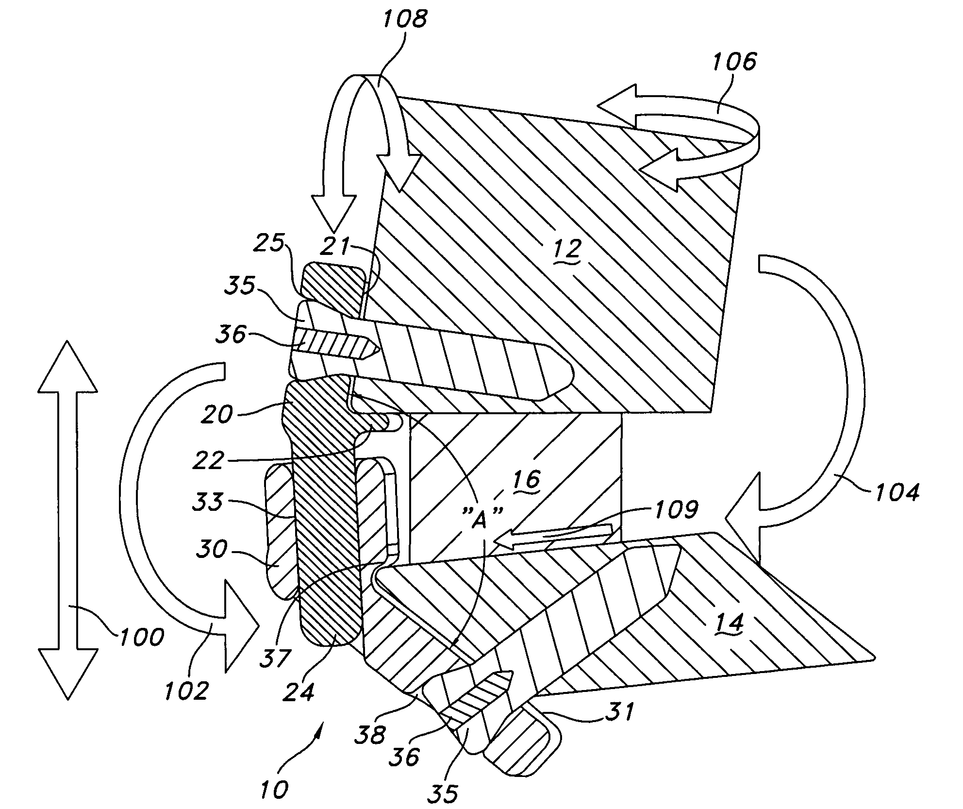
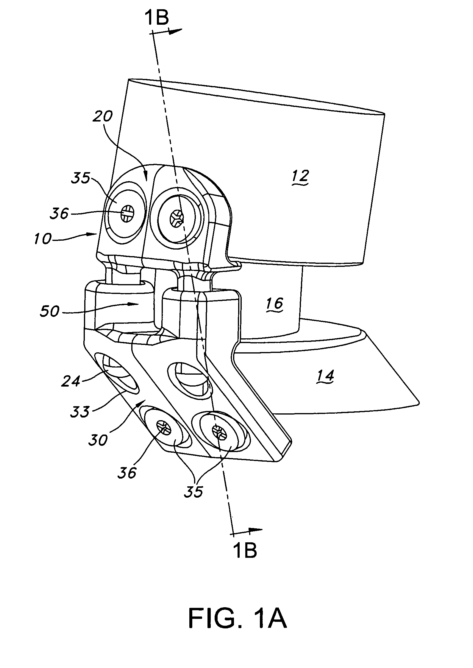
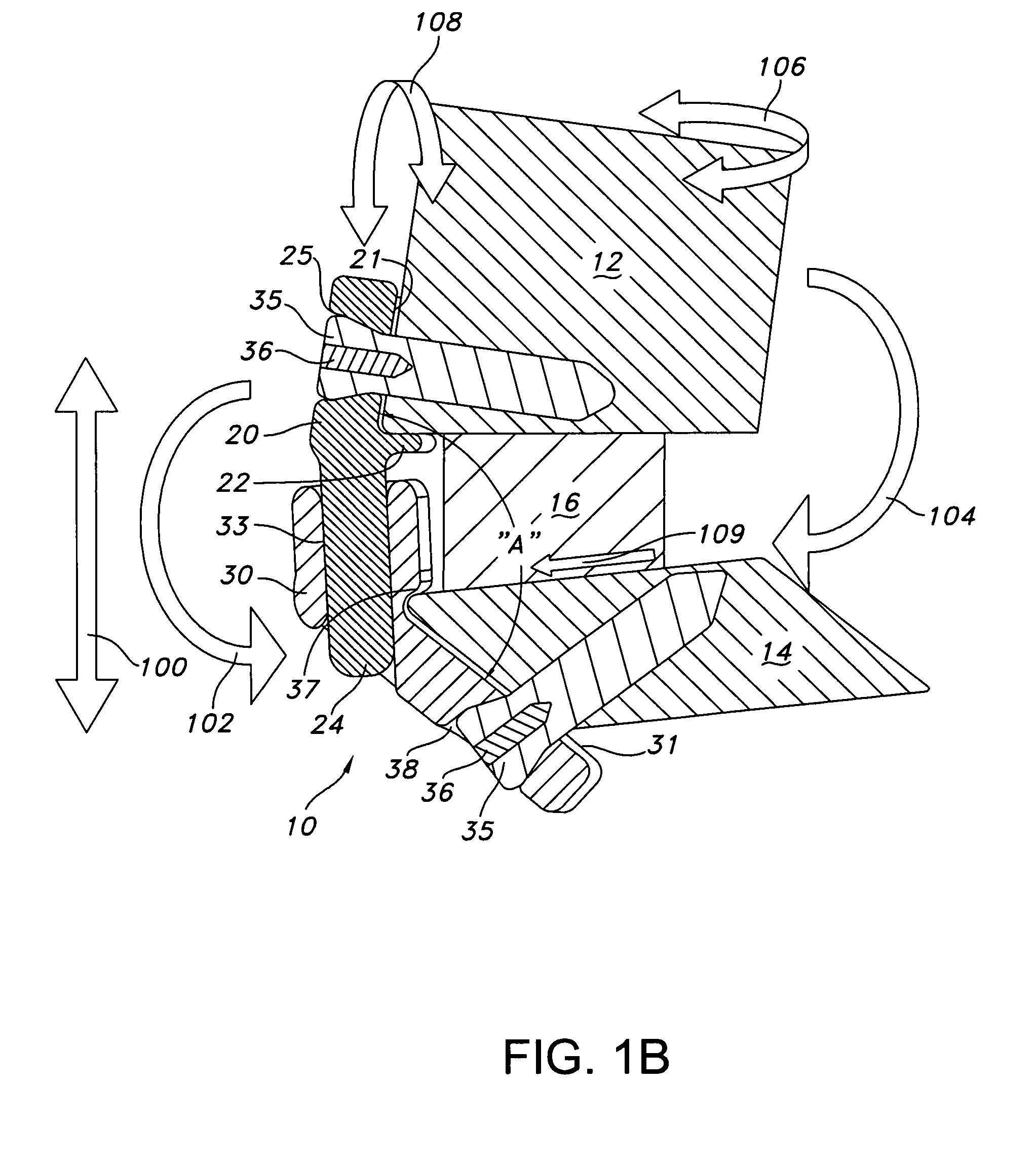
[0027]Referring generally to the figures, according to an aspect of the invention, a bone stabilization device 10, 110, 210 comprises an inferior plate 30, 130, 230 having a vertebral mating surface 31 for positioning against a vertebrae 14, and the inferior plate defines a recess 33, 133. The device further comprises a superior plate 20, 120, 220 having a vertebral mating surface 21 for positioning against an adjacent vertebrae 12. The superior plate includes a projection 24 configured to travel in the recess 33, 133 of the inferior plate. The vertebral mating surface 31 of the inferior plate is non-coplanar with respect to the vertebral mating surface 21 of the superior ...


PUM


Abstract

A dynamic vertebral stabilization device for constraining motion of adjacent vertebrae is provided. The bone stabilization device comprises a first plate having a vertebral mating surface for positioning against a vertebrae, wherein the first plate defines a recess. The device further comprises a second plate having a vertebral mating surface for positioning against an adjacent vertebrae. The second plate includes a projection configured to travel in the recess of the first plate. The vertebral mating surface of the first plate is non-coplanar with respect to the vertebral mating surface of the second plate.

Description

FIELD OF THE INVENTION[0001]The present invention relates to a dynamic stabilization device for anterior lower lumbar vertebral fusion, and a method for installing the dynamic stabilization device to the lower lumbar vertebrae.BACKGROUND OF THE INVENTION[0002]The human spine is composed of cervical, thoracic, lumbar and sacrum vertebrae. The neck region of the spine is known as the cervical spine, which consists of seven vertebrae, which are abbreviated C1 through C7 (top to bottom). Beneath the last cervical vertebra are twelve vertebrae of the thoracic spine. The thoracic vertebrae are abbreviated T1 through T12 (top to bottom). Beneath the last thoracic vertebra are five lumbar vertebrae, abbreviated L1 through L5. The size and shape of each lumbar vertebra is designed to carry most of the body's weight. Each structural element of a lumbar vertebra is bigger, wider and broader than similar components in the cervical and thoracic regions. Beneath the lumbar spine, five sacral vert...

Claims


Application Information

Patent Timeline
IPC IPC(8): A61F2/30
CPCA61B17/7059A61F2/4455A61B17/8023
Inventor FREEDMAN, SCOTTWING, CHARLES
Owner AESCULAP IMPLANT SYST
Why Eureka
Try Eureka