Motorcycle foot peg and boot cleat assembly

a technology for motorcycles and foot pegs, which is applied in the field of motorcycle foot pegs and boot cleat assemblies, can solve the problems of riding on the back, the legs, hands, legs, and arms of the rider, and the feet of the rider not being able to prevent the pegs from pulling off, so as to achieve less body stress, less fatigue, and more control

Inactive Publication Date: 2008-07-31
BOEHMKE STEVEN L +3
View PDF1 Cites 39 Cited by
  • Summary
  • Abstract
  • Description
  • Claims
  • Application Information

AI Technical Summary

Benefits of technology

[0018]The invention provides a foot peg and boot for motorcycles that allows the rider to clip in securely. This gives the motorcycle rider more control, less fatigue, more stunts, the ability to bunny hop the motorcycle, and less body stress. This extra assistance helps the rider to conserve energy and reduce fatigue and therefore retain a higher level of concentration.

Problems solved by technology

For example, motorcycle foot pegs only provide a surface to stand on, and do not prevent the rider's feet from pulling off of the pegs.
Especially on longer rides, this is tiring for the rider's legs, hands, and arms, and causes strain on the rider's neck and back.
Furthermore, it can be dangerous if the rider loses grip and his feet lose contact with the pegs.
Smith's peg does not provide any means of retaining a boot onto the peg.

Method used


Image

  • Motorcycle foot peg and boot cleat assembly
  • Motorcycle foot peg and boot cleat assembly
  • Motorcycle foot peg and boot cleat assembly

Examples


Embodiment Construction

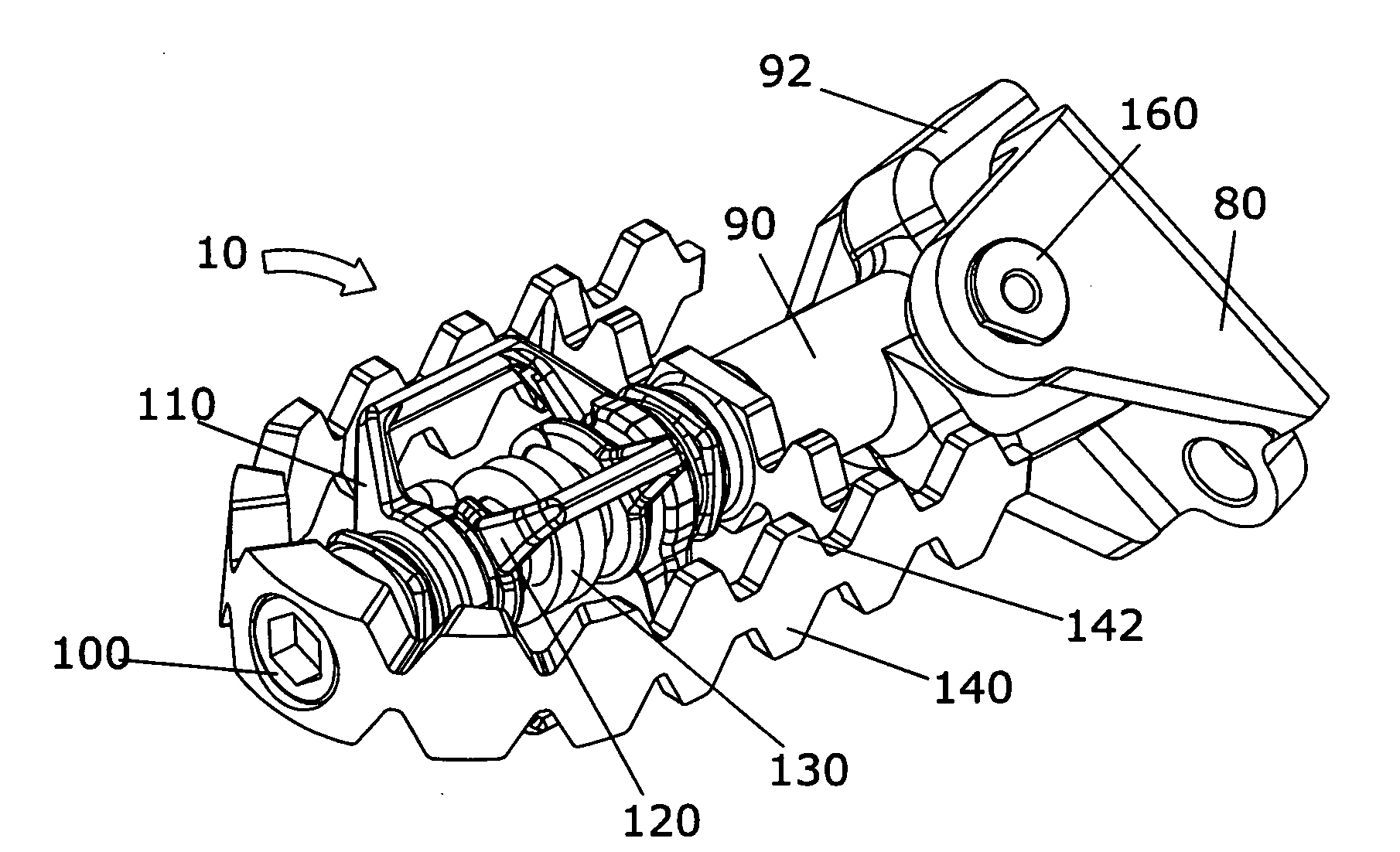
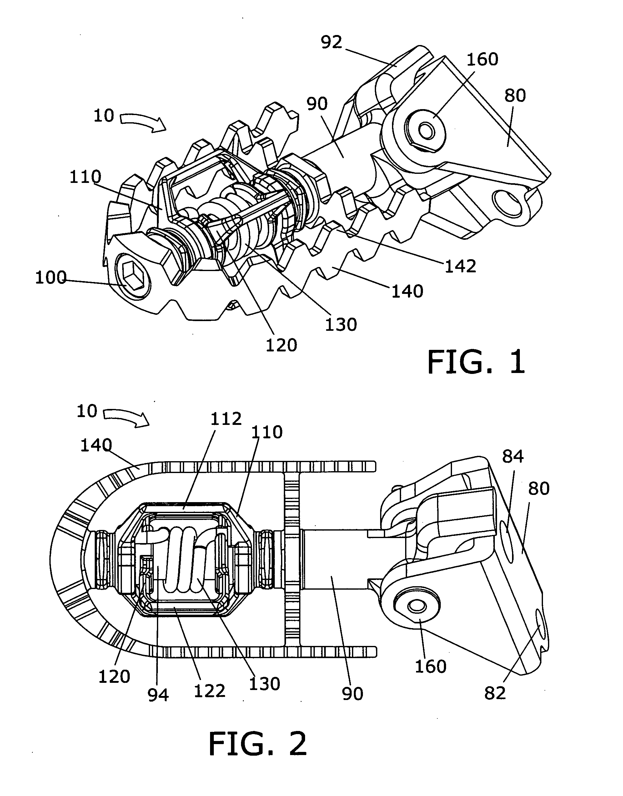
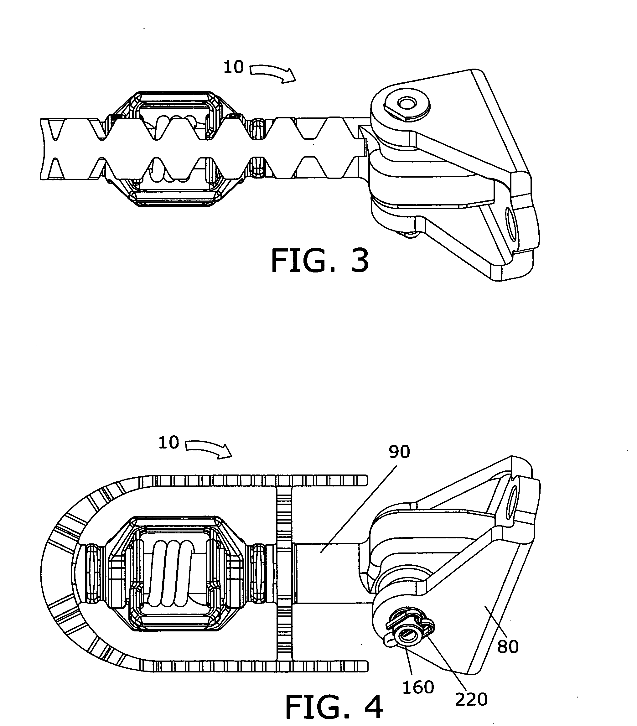
[0041]The present invention may be understood by referring to FIGS. 1-19. By way of example, referring to FIGS. 1 to 19, it will be seen that the foregoing and other objects are attained, according to the present invention by a motorcycle foot peg 10, which is comprised of a shaft 90 connected to a bracket 80 via a pin 160, cotter pin 220, platform 140, outer latch 110, inner latch 120, spring 130, and screw 100. Platform 140 swivels on shaft 90. Spring 130 biases outer latch 110 to be held substantially perpendicular to inner latch 120, and swivels on shaft 90. When mounted to a motorcycle frame, foot peg 10 enables a motorcycle rider to fixedly engage into the foot peg via fore and aft cleats 230 and 70 on the bottom of his or her motorcycle boots 40 and 60. To release from the foot peg 10, the rider twists his or her boots 40 and 60 past a certain angle. Platform 140 pivots to expose either side of the platform and make proper contact between the bottom of the boot and the platfo...


PUM


Abstract

A motorcycle foot peg is comprised of a shaft connected to a bracket via a pin and a cotter pin, a platform, an outer and inner latch, a spring, and a screw. A platform swivels on the shaft. The spring biases the outer latch to be held substantially perpendicular to the inner latch, and swivels on the shaft. When mounted to a motorcycle frame, the foot peg enables a motorcycle rider to fixedly engage their feet into the foot peg via fore and aft cleats on the bottom of their motorcycle boots. To release from the foot peg, the rider twists their boots past a certain angle. The platform pivots to expose either side of the platform and make proper contact between the bottom of the boot and the platform. Platform teeth give grip between the boot and the platform when rider is not engaged to the foot peg. A shaft leg prevents the foot peg from pivoting up and back relative to the motorcycle frame. A first cleat is mounted towards the front of a motorcycle boot and a second cleat rearward from the first. Screws secure cleats to the bottom of the motorcycle boot. Slots allow the cleat to be adjusted fore and aft. A rider clips into the forward cleat in order to absorb bumps in the terrain, and clips into the rearward cleat in order to operate the gear shift lever or operate the foot brake. For longer rides for comfort, it may be desirable to switch between being clipped into the forward and rearward cleats.

Description

BACKGROUND OF THE INVENTION[0001]1. Field of the Invention[0002]This invention relates to motorcycles and more particularly to an improvement in foot pegs for motorcycles, including two and three wheeled motorcycles and also four wheeled all terrain vehicles which are ridden in a manner similar to motorcycles.[0003]2. Background Art[0004]As is well-known, most motorcycle assemblies include a frame having a seat on which a rider sits in a straddle fashion. Foot pegs are carried at the lower end of the frame at opposite sides thereof for the rider to place his feet when riding. Frequently, controls for operating certain components of the motor cycle, such as a rear wheel brake or gear shift, are located in close proximity to the foot pegs. This allows the operator to foot activate the controls when desirable.[0005]It is common for motorcycle foot pegs to vary in appearance depending on intended application. Overall their basic design remains the same, that is, they provide a fixed pro...

Claims


Application Information

Patent Timeline
Patent Type & Authority Applications(United States)
IPC IPC(8): B62J25/00
CPCB62J25/00A43B5/145B62J25/04B62M3/086
Inventor BOEHMKE, STEVEN L.HERMANSEN, FRANKWINEFORDNER, CARLHERRICK, ANDREW
Owner BOEHMKE STEVEN L
Why Eureka
Try Eureka