Modular telecommunications frame and enclosure assembly

a technology of which is applied in the field of modular telecommunications frame and enclosure assembly, can solve the problems of increased movement and flexing of the rear side cabling, inability to warrant floor-to-ceiling relay rack, and difficulty in front side access to patch panels

Inactive Publication Date: 2008-07-31
ORTRONICS INC
View PDF19 Cites 46 Cited by
  • Summary
  • Abstract
  • Description
  • Claims
  • Application Information

AI Technical Summary

Benefits of technology

[0012]In an exemplary embodiment where the support frame is mounted within a cabinet, at least one of the walls is hingedly attached to a rear side of the cabinet by a pair of aligned pivoting hinges and is partially detachably connected to a front side of the cabinet by a pair of aligned disengaging latches adapted to allow the hingedly attached

Problems solved by technology

In many installations, a floor-to-ceiling relay rack is not warranted for the number of panels which are to be utilized.
Cabinets having patch panels mounted on the back side of the front door create several complications.
When the door is in an open position, front side access to the patch panels is difficult.
A further drawback associated with front door mounting involves increased movement and flexing of the rear side cabling associated with the patch panel.
This creates increas

Method used


Image

  • Modular telecommunications frame and enclosure assembly
  • Modular telecommunications frame and enclosure assembly
  • Modular telecommunications frame and enclosure assembly

Examples


Embodiment Construction

)

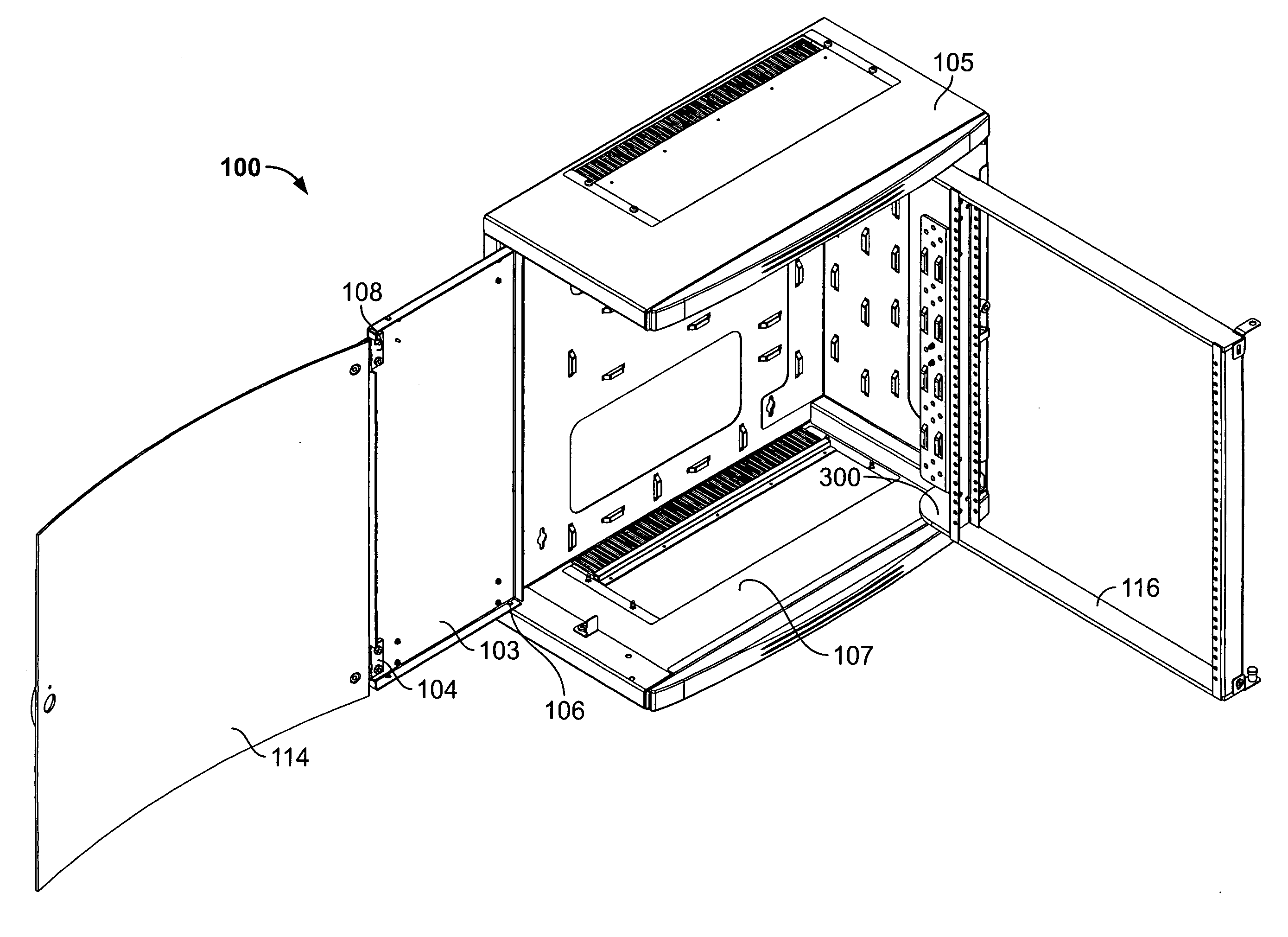
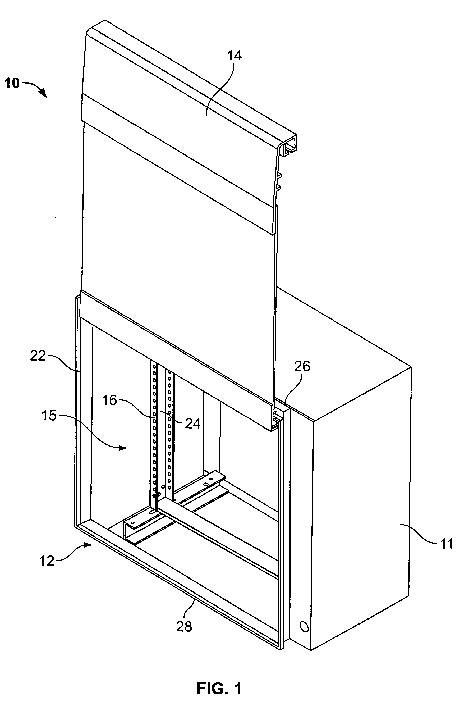
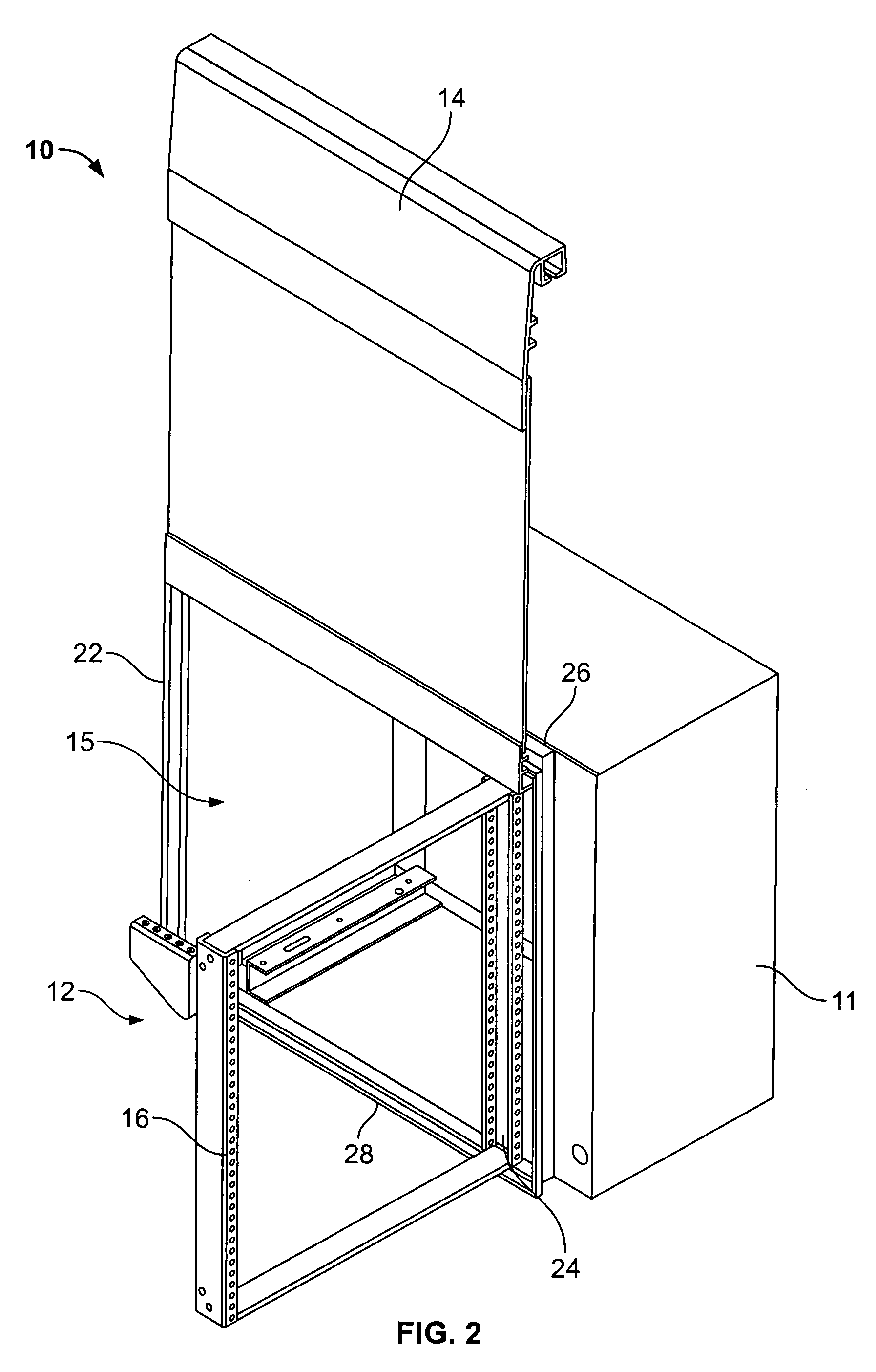
[0033]The present disclosure provides for assemblies and methods for mounting telecommunication equipment effectively within various environments, including specifically a drop ceiling, a raised floor and / or a wall rack. An exemplary telecommunications frame assembly according to the present disclosure is operable to be utilized in at least three unique orientations: (i) mounted vertically with respect to a wall, wall rack and / or cabinet; (ii) mounted horizontally within a drop ceiling; and / or (iii) mounted horizontally within a raised floor. The frame assemblies allow for vertical and horizontal mounting of patch panels and telecommunications equipment. A frame assembly according to the present disclosure can be a standalone exposed assembly or fitted within an enclosure or cabinet.

[0034]An exemplary embodiment according to the present disclosure includes a cabinet having a built-in mounting frame. The present disclosure also provides for a cabinet adapted to enclose a standalone ...


PUM

PropertyMeasurementUnit
Angleaaaaaaaaaa
Speedaaaaaaaaaa

Abstract

Assemblies and methods for mounting telecommunications equipment, such as patch panels is provided. A mounting assembly is disclosed including a swing gate adapted to host a plurality of telecommunications equipment. The swing gate is hingedly attached to a support frame by a pair of aligned hinges adapted to allow the swing gate to open and close. The support frame includes support members defining an opening for fitting telecommunications equipment within the support frame when the swing gate is closed. The support frame is adapted to be mounted with respect to various mounting locations such as a support structure of a raised floor or drop ceiling, a wall, and/or a cabinet. A cabinet adapted to enclose the support frame includes walls defining a cavity. At least one of the walls is a front door adapted to open and close and allow access to the swing gate when the front door is open. The cabinet is adapted to be mounted with respect to a raised floor, drop ceiling, or a wall. The hinges connecting the swing gate to the support frame are aligned crooked arm hinges positioning the swing gate off set from the front face of the support frame. An exemplary assembly includes a cabinet having walls defining a cavity. One of the walls is a front door adapted to open and close. A swing gate is hingedly connected to the cabinet by a pair of aligned crooked arm hinges. The cabinet is plenum rated defining at least one fire stopped cable opening for drop ceiling mounting.

Description

BACKGROUND[0001]1. Technical Field[0002]The present disclosure relates to assemblies and methods for efficient and accessible mounting of telecommunications equipment within a ceiling, floor and / or a telecommunications closet.[0003]2. Background Art[0004]Wiring and connected hardware are an integral part of a typical commercial building telecommunications wiring system. Wiring standards of Category 5 Transmission, for example, require that items, such as, modular jack panels be mounted for easy installation and service. A typical piece of equipment upon which modular jack panels or patch panels are mounted is a floor-to-ceiling relay rack. In many installations, a floor-to-ceiling relay rack is not warranted for the number of panels which are to be utilized.[0005]A well-known piece of equipment for mounting a smaller number of panels is a wall rack typically mounted on a vertical wall. A wall rack generally includes a support frame which is fixed relative to the wall and a mounting ...

Claims


Application Information

Patent Timeline
IPC IPC(8): A47B81/00
CPCH04Q1/10H05K7/186Y10T29/49826H04Q1/06H04Q1/026H04Q1/021
Inventor MARTICH, MARK E.LARSEN, LARS R.LEVESQUE, STEWART A.
Owner ORTRONICS INC
Why Eureka
Try Eureka