Single arm tow mirror assembly

a technology of single arm and assembly, applied in the field of vehicle mirrors, can solve problems such as acceleration of wear and tear

Active Publication Date: 2008-07-31
VISIOCORP PATENTS S A R L +1
View PDF3 Cites 2 Cited by
  • Summary
  • Abstract
  • Description
  • Claims
  • Application Information

AI Technical Summary

Problems solved by technology

Therefore, unnecessary forces are being applied to the mechanism that moves the mirror assembly, which will eventually accelerate its wear and tear.

Method used


Image

  • Single arm tow mirror assembly
  • Single arm tow mirror assembly
  • Single arm tow mirror assembly

Examples


Embodiment Construction

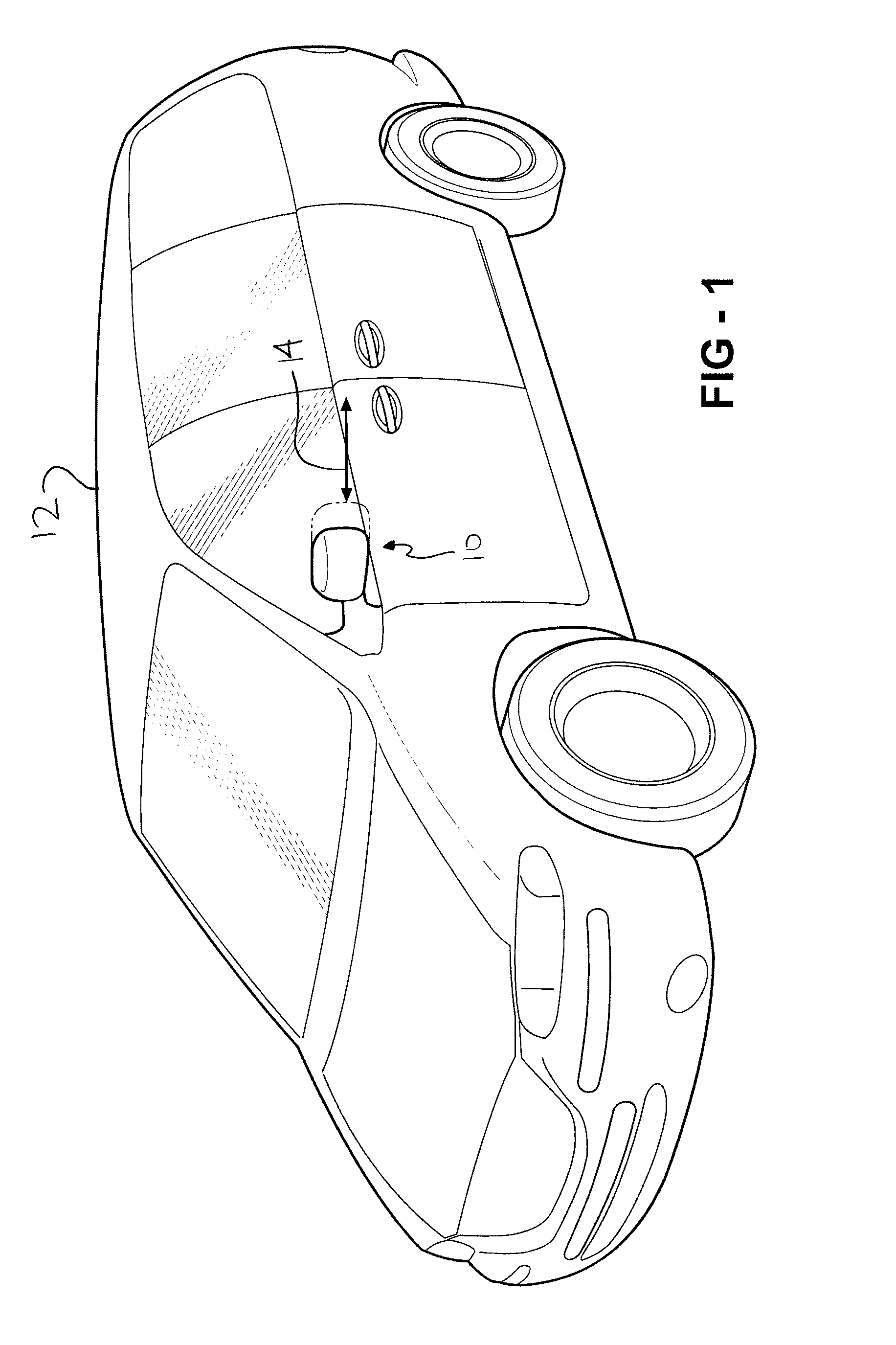
[0015]An external rearview mirror assembly according to the invention is generally indicated at 10 in FIG. 1. The external rearview mirror assembly 10 is a side mirror that allows an occupant of a motor vehicle 12 to see rearward of the motor vehicle 12 without having to turn the operator's head completely around. This provides an opportunity for the operator of the motor vehicle 12 to view areas rearward of the motor vehicle 12 without totally losing sight of the space directly in front of the motor vehicle 12. While it is contemplated that the external rearview mirror assembly 10 may be mounted on both sides of the motor vehicle, only one is shown in FIG. 1. Similar features will be, however, incorporated into external rearview mirror assemblies 10 that are fixedly secured to the passenger side of the motor vehicle 12.

[0016]A bidirectional arrow 14 illustrates the ability of the external rearview mirror assembly 10 to move from a retracted use position to an extended use position ...


PUM


Abstract

An external rearview mirror assembly is fixedly secured to a motor vehicle. The external rearview mirror assembly includes a mounting bracket which is fixedly secured to the motor vehicle. An arm is pivotally secured to the mounting bracket. The arm defines an elongated channel having an upper arm surface, a lower arm surface, and an intermediate arm surface disposed between the upper and lower arm surfaces. A case frame extends between a bracket and a distal end. The case frame defines an elongated channel for receiving the elongated channel therein. A mirror is movaably secured to the distal end of the case frame to provide a view rearward of the motor vehicle.

Description

BACKGROUND ART[0001]1. Field of the Invention[0002]The invention relates generally to a vehicle mirror. More particularly, the invention relates to a vehicle mirror that is movable between extended and retracted positions.[0003]2. Description of the Related Art[0004]Mirror assemblies that extend out the sides of motor vehicles are used to assist the operator thereof to quickly view the surroundings of the motor vehicle without diverting attention from the direction in which the motor vehicle is being driven. Mirror assemblies include features such as turn signals and heaters to further aid the operator in operating the vehicle in a safe manner.[0005]With the advent of larger sized vehicles and an increased capacity to tow large, heavy loads, there is the need to produce mirror assemblies that have the ability to provide the operator of the motor vehicle with a view beyond the cargo being towed. This is typically accomplished by moving the mirror assembly further away from the motor ...

Claims


Application Information

Patent Timeline
Patent Type & Authority Applications(United States)
IPC IPC(8): G02B7/182
CPCB60R1/002
Inventor HENION, PAUL R.
Owner VISIOCORP PATENTS S A R L
Why Eureka
Try Eureka