
Omni-directional radio frequency identification tag antenna and radio frequency identification tag

A radio frequency identification tag and antenna technology, applied in the field of omnidirectional radio frequency identification tag antenna, can solve the problem that the antenna is difficult to achieve "omnidirectional"

Inactive Publication Date: 2012-07-11
QUINTET DIGITAL CORP
View PDF4 Cites 4 Cited by
  • Summary
  • Abstract
  • Description
  • Claims
  • Application Information

AI Technical Summary

Problems solved by technology

[0005] The purpose of the present invention is to provide an omnidirectional radio frequency identification tag antenna to solve the problem that the existing antenna is difficult to realize "omnidirectional" in the true sense

Method used


Image

  • Omni-directional radio frequency identification tag antenna and radio frequency identification tag
  • Omni-directional radio frequency identification tag antenna and radio frequency identification tag
  • Omni-directional radio frequency identification tag antenna and radio frequency identification tag

Examples


Embodiment Construction

[0034] The present invention will be described in detail below in conjunction with the accompanying drawings.

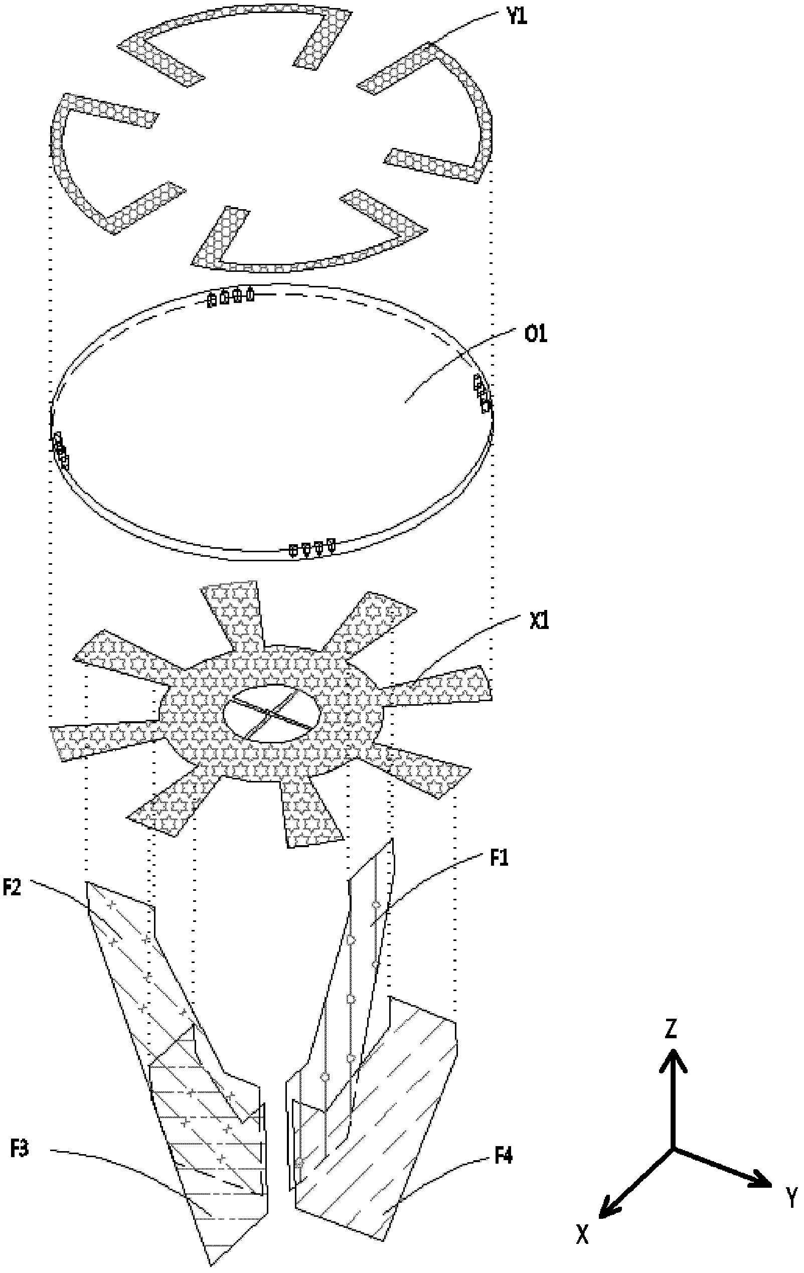
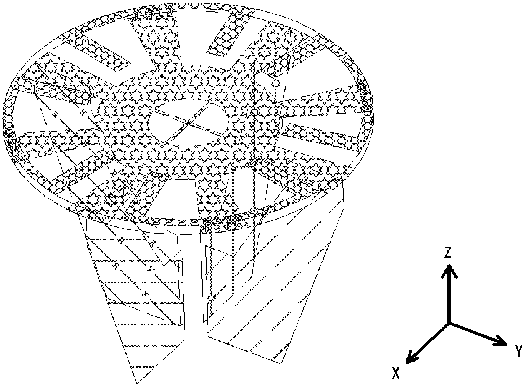
[0035] See figure 1 and figure 2 , which are respectively an isometric assembly diagram and an isometric perspective view of the omnidirectional radio frequency identification tag antenna of the present invention, the omnidirectional radio frequency identification tag antenna includes a tag substrate O1, a resonant circuit surface circuit pattern part X1, a circuit resonant arm The surface circuit pattern part Y1 and four metal resonant arms F1, F2, F3, F4, the resonant circuit surface circuit pattern part X1 and the circuit resonant arm surface circuit pattern part Y1 are all set on the label substrate O1, and the four metal resonant arms F1 , F2, F3 and F4 are all electrically connected to the circuit pattern part X1 on the resonant circuit surface.

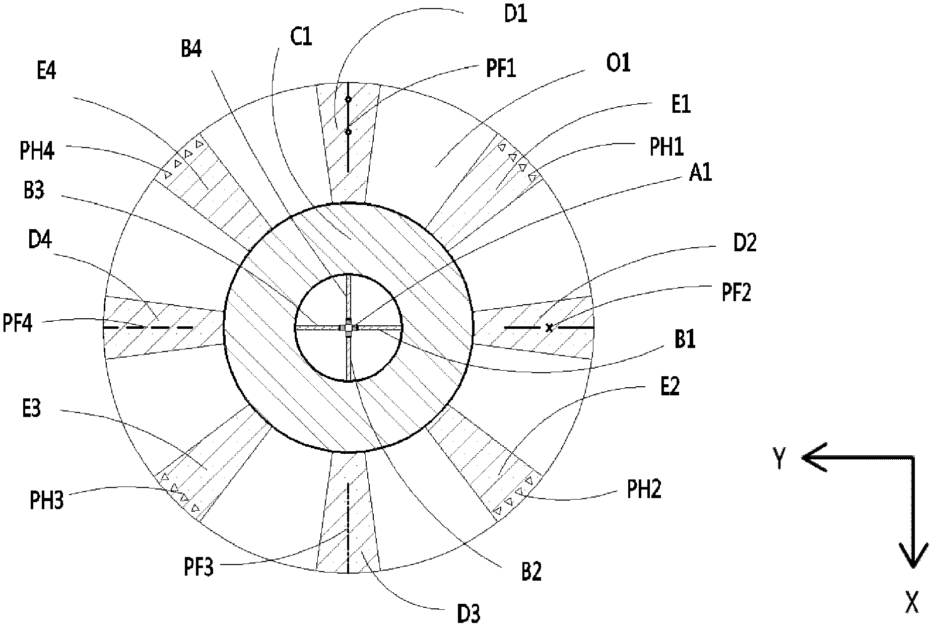
[0036] See image 3 , which is figure 1 The schematic plan view of the circuit pattern part of the resonant ci...


PUM


Abstract

The invention provides an omni-directional radio frequency identification tag antenna, comprising a tag substrate, a resonance loop surface circuit pattern part, a circuit resonance arm surface circuit pattern part and four metal resonance arms, wherein the resonance loop surface circuit pattern part is arranged on the tag substrate and composed of at least one resonance loop; the circuit resonance arm surface circuit pattern part is arranged on the tag substrate and composed of at least two circuit resonance arms, the circuit resonance arms are connected with the resonance loop surface circuit pattern part and the circuit resonance arms correspond to each other pairwise and form a first plane radiation surface; four metal harmonic arms are all connected with the resonance loop surface circuit pattern part, correspond to each other pairwise and form a second plane radiation surface and a third plane radiation surface. The omni-directional radio frequency identification tag antenna has radiation surfaces on three coordinate axes and the corresponding radiation arms are uniformly distributed at phase points at intervals of 45 degrees, the generated antenna effective gain chart covers all the directions of the spherical surface, and thus the antenna is named a real omni-directional antenna.

Description

technical field [0001] The invention relates to an antenna of a radio frequency identification tag, in particular to an omnidirectional radio frequency identification tag antenna. Background technique [0002] RFID is the abbreviation of radio frequency identification technology (Radio Frequency Identification). RFID is commonly known as electronic tags. RFID technology is a non-contact two-way communication that uses radio frequency signals to automatically identify target objects and obtain relevant information. Wireless communication technology of information. With the advancement of science and technology, RFID has been involved in all aspects of people's daily life, and has been widely used in many fields such as industrial automation, commercial automation, traffic calculation control management, such as train traffic monitoring systems, expressway automatic toll systems, items Management, assembly line production automation, access control systems, financial transact...

Claims


Application Information

Patent Timeline
Patent Type & Authority Applications(China)
IPC IPC(8): H01Q1/38H01Q19/12H01Q1/22G06K19/077
CPCH01Q7/00G06K19/077H01Q1/2225
Inventor SHI JIYUAN
Owner QUINTET DIGITAL CORP
Learn More