Automatic C-shaped-arm bearing laminating device

A technology for bonding devices and bearings, which is applied in the direction of bearing components, shafts and bearings, rigid supports of bearing components, etc., can solve the problems of laborious sliding, unsmooth sliding, high precision of bearing seat processing and installation, and increase the sliding area , Easy assembly, smooth installation effect

Pending Publication Date: 2019-04-26
NANJING KPOUR TECH CO LTD
View PDF0 Cites 2 Cited by
  • Summary
  • Abstract
  • Description
  • Claims
  • Application Information

AI Technical Summary

Problems solved by technology

The existing sliding connection method only has four deep groove ball bearings for up and down sliding and left and right sliding. The weight is inconsistent; there are only four deep groove ball bearings in each direction as the sliding fulcrum, resulting in unsmooth sliding, and it is laborious to slide withi

Method used


Image

  • Automatic C-shaped-arm bearing laminating device
  • Automatic C-shaped-arm bearing laminating device
  • Automatic C-shaped-arm bearing laminating device

Examples


Embodiment

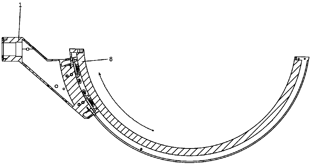
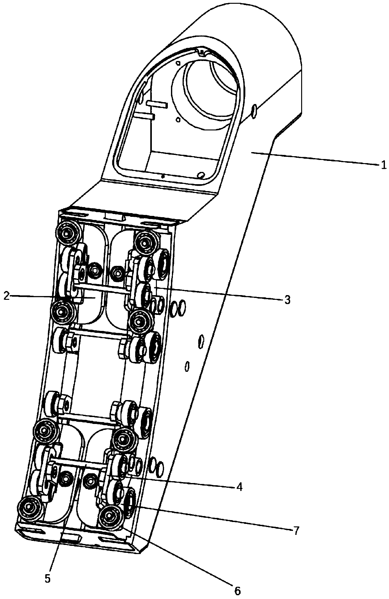
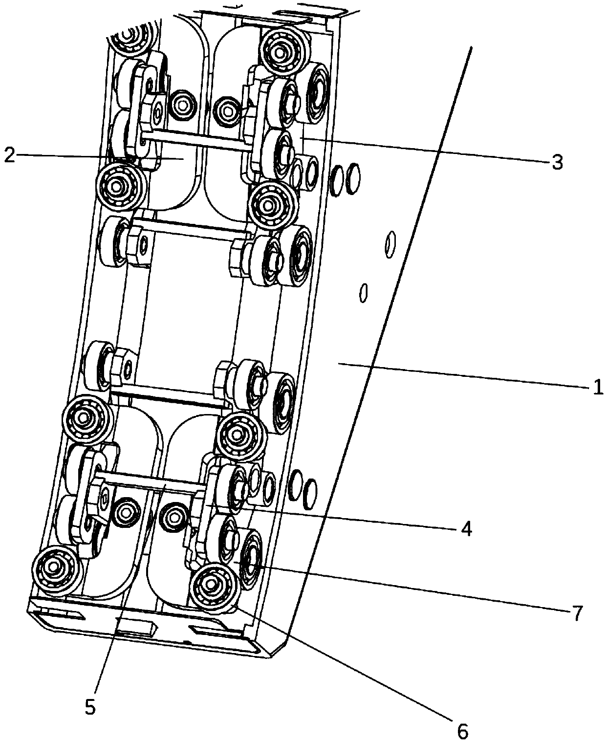
[0023] Such as Figure 1-3 As shown, the present invention provides a C-arm bearing automatic fitting device, including a straight arm 1 and a C arm 8, wherein the straight arm 1 is connected to the C arm 8; the straight arm 1 is connected to the C arm 8 in a non- Fixed connection; several sets of straight arm upper roller rods 2 are installed on the bottom of the straight arm 1, wherein the outer sides of the straight arm upper roller rods 2 are equipped with straight arm lower roller rods 3; the inner sides of the straight arm lower roller rods 3 are all installed There is a roller bar 4 in the straight arm; the first deep groove ball bearing 6 is installed on the outer side of the roller bar 4 in the straight arm. Further, a second deep groove ball bearing 7 is installed on one side of the first deep groove ball bearing 6, wherein the relative angle between the first deep groove ball bearing 6 and the second deep groove ball bearing 7 is 90 degrees.

[0024] Specifically, ...


PUM


Abstract

The invention discloses an automatic C-shaped-arm bearing laminating device. The automatic C-shaped-arm bearing laminating device comprises a straight arm and a C arm, wherein the straight arm is connected with the C arm in a non-fixed manner, and multiple sets of straight-arm upper roller rods are installed at the bottom of the straight arm. A straight-arm lower roller rod is installed on the outer side of each straight-arm upper roller rod, a straight-arm middle roller rod is installed on the inner side of each straight-arm lower roller rod, and a first deep groove ball bearing is installedon the outer side of each straight-arm middle roller rod. According to the automatic C-shaped-arm bearing laminating device, by means of the straight-arm middle connecting rod, the straight-arm lowerconnecting rod and the attached deep groove ball bearings, it can be guaranteed that 20 deep groove ball bearings are used for bearing when the C arm slides up and down, 8 deep groove ball bearings are used for bearing when the C arm slides left and right, and therefore the weights of the C arm, a ball pipe and a detector can be well dispersed on the whole straight-arm surface at each sliding position; and each deep groove ball bearing can do minor movement, assembly is convenient to achieve, and the C arm can be installed more smoothly in the installation process.

Description

technical field [0001] The invention relates to a sliding connection device for a C-shaped arm and a straight arm, in particular to an automatic bonding device for a C-shaped arm bearing. Background technique [0002] In the existing sliding connection between the C-arm and the straight arm, the sliding connection is generally completed by using bearing housings with deep groove ball bearings, and usually two sets of bearing housings are respectively located at the upper and lower ends of the straight arm arc. The upper and lower sliding bearings are responsible for carrying and making the C-arm slide in the vertical state of the straight arm, and the left and right sliding bearings are responsible for carrying and making the C-arm slide in the horizontal state of the straight arm. The existing sliding connection method only has four deep groove ball bearings for up and down sliding and left and right sliding. The weight is inconsistent; there are only four deep groove ball...

Claims


Application Information

Patent Timeline
IPC IPC(8): F16C35/04
CPCF16C35/04
Inventor 于灵芝
Owner NANJING KPOUR TECH CO LTD
Why Eureka
Try Eureka