Magnetic encoder having a stable output property with unsaturated magnetic sensor

a technology of unsaturated magnetic sensors and encoders, applied in the field of magnetic encoders, can solve the problems of unintentional output setoff, reducing resolution by half, and achieving sufficient output, and achieve stable output, high resolution, and high reliability.

Active Publication Date: 2008-07-31
HITACHI METALS LTD
View PDF3 Cites 8 Cited by
  • Summary
  • Abstract
  • Description
  • Claims
  • Application Information

AI Technical Summary

Benefits of technology

[0012]An object of the present invention is therefore to provide a magnetic encoder having high resolution and having high reliability with little change in output even at the occurrence of variations in the magnetic gap between the magnetic sensor and the magnetic medium.
[0013]To fabricate a magnetic encoder configured of a magnetic medium periodically magnetized and a magnetic sensor formed of plural magnetoresistive elements, each using a Spin-valve type GMR film, the present invention uses the magnetoresistive element that exhibits a characteristic response for magnetic field. Generally, the magnetoresistive element is often desired to have linear magnetic parametric performance for signal magnetic field. However, the present invention fabricates and uses the magnetoresistive element having nonlinear magnetoresistive properties for signal magnetic field. Specifically, the present invention uses the magnetoresistive element that satisfies the equation, H10-50<H50-90, where H10-50 represents a magnetic field required for a resistance change from ΔR×10% to ΔR×50% with respect to a maximum amount of resistance change (hereinafter referred to simply as “ΔR”) in process of a resistance change occurring according to an external magnetic field parallel to the direction of magnetization of the ferromagnetic pinned layer, and H50-90 represents a magnetic field required for a resistance change from ΔR×50% to ΔR×90%. In other words, the magnetoresistive element for use in the present invention has high sensitivity in a changing region where the amount of resistance change increases from ΔR×10% to ΔR×50% in process of a transition of the amount of resistance change from zero to ΔR, and has low sensitivity in a changing region where the amount thereof increases from ΔR×50% to ΔR×90%. Preferably, the present invention uses the magnetoresistive element that satisfies the equation, 1.5<H50-90 / H10-50<4.0. This enables suppressing the unintentional output setoff involved in the superposition of outputs. Moreover, the suppression of the output setoff involved in the superposition of outputs enables achieving stable output characteristics, even at the occurrence of variations in the magnetic gap between the magnetic sensor and the magnetic medium.
[0016]The present invention enables achieving a magnetic encoder capable of achieving stable output, suitable for high resolution, and having high reliability, even at the occurrence of variations in the magnetic gap between the magnetic medium and the magnetic sensor.

Problems solved by technology

However, the use of the Spin-valve type GMR element in place of the AMR element or the coupled GMR element has the problem of reducing resolution by half.
However, this superposition has difficulty in achieving sufficiently high output because it can possibly cause unintentional output setoff.
On the other hand, in process of a series of examinations, it has been shown that too narrow a magnetic gap also causes a decrease in the output from the magnetic sensor.
In other words, the prior art has difficulty in achieving the magnetic encoder suitable for high resolution and also having high reliability, because of being incapable of achieving stable high output at the occurrence of fluctuations in the magnetic gap between the magnetic sensor and the magnetic medium.

Method used


Image

  • Magnetic encoder having a stable output property with unsaturated magnetic sensor
  • Magnetic encoder having a stable output property with unsaturated magnetic sensor
  • Magnetic encoder having a stable output property with unsaturated magnetic sensor

Examples


first embodiment

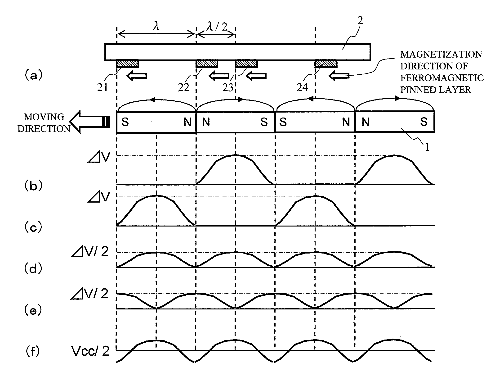
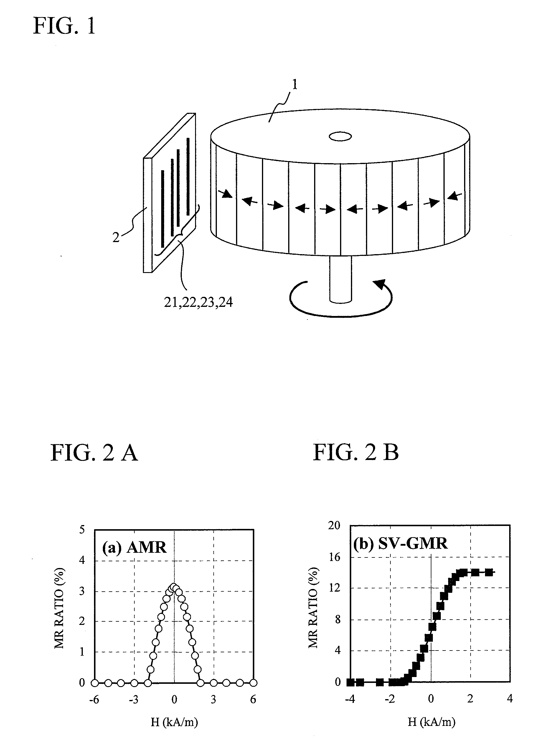
[0046]FIG. 1 illustrates, in schematic form, the configuration of a magnetic encoder according to the present invention. The magnetic encoder includes a magnetic medium 1, and a magnetic sensor 2 that moves relative to the magnetic medium 1, facing the magnetic medium 1 with a predetermined gap in between, and the magnetic medium 1 is magnetized in alternating multipolar form in the direction of relative movement thereof with respect to the magnetic sensor 2.

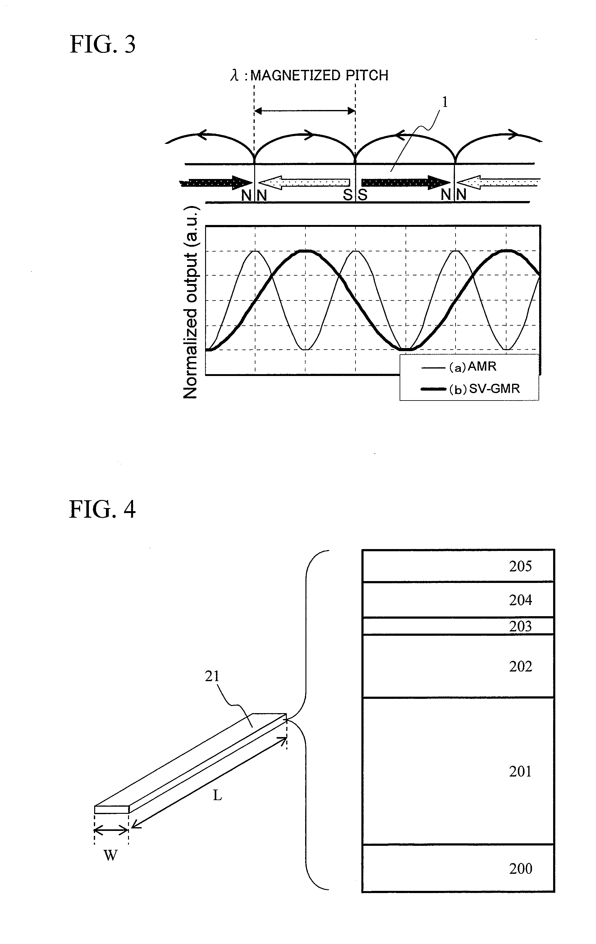
[0047]The magnetic sensor 2 includes a magnetoresistive element 21 using at least a Spin-valve type GMR film. FIG. 4 illustrates, in schematic form, the configuration of the magnetoresistive element 21. The Spin-valve type GMR film that constitutes the magnetoresistive element 21 has a multilayer structure including at least a ferromagnetic pinned layer 202, a non-magnetic intermediate layer 203, and a ferromagnetic free layer 204, which are stacked one on top of another. Furthermore, an antiferromagnetic layer 201 may be formed...

second embodiment

[0077]As previously mentioned, the magnetoresistive element is of such a shape that the pattern length L is very great as compared to the pattern width W. The narrower pattern width W is more favorable in particular for an increase in the resolution for detection of the signal magnetic field from the magnetic medium. However, an increase in an aspect ratio of the pattern length L to the pattern width W results in the shape anisotropy, which causes the induction, into the ferromagnetic free layer, of the uniaxial magnetic anisotropy such that the direction of the pattern length L coincides with the axis of easy magnetization. Thus, the effective Hk* value of the magnetoresistive element becomes larger than the Hk value of the ferromagnetic free layer in itself. This is not desirable because it not only reduces the sensitivity of the magnetoresistive element to the magnetic field but also causes output setoff and hence a decrease in output at the time of superposition of outputs from ...


PUM

PropertyMeasurementUnit
thicknessaaaaaaaaaa
thicknessesaaaaaaaaaa

Abstract

The present invention provides a magnetic sensor suitable for high resolution and having high reliability by achieving stable output even at the occurrence of variations in a gap between a magnetic medium and the magnetic sensor, and a magnetic encoder using the magnetic sensor. The present invention uses a magnetoresistive element having magnetoresistive properties that satisfy the inequation, H10-50<H50-90, where H10-50 represents a magnetic field required for a resistance change from ΔR×10% to ΔR×50% with respect to a maximum amount of resistance change ΔR on a magnetoresitance effect curve, and H50-90 represents a magnetic field required for a resistance change from ΔR×50% to ΔR×90%.

Description

CLAIM OF PRIORITY[0001]The present application claims priority from Japanese application JP 2007-021372 filed on Jan. 31, 2007, the content of which is hereby incorporated by reference into this application.BACKGROUND OF THE INVENTION[0002]1. Technical Field[0003]The present invention relates to a magnetic sensor having a Spin-valve type giant magnetoresistive element and a magnetic encoder using the same.[0004]2. Background Art[0005]Recently, there have been strong demands that a magnetic encoder for use in consumer electronics equipment such as a digital still camera and an ink jet printer achieves high resolution and low power consumption in addition to small size and low price.[0006]Heretofore, an anisotropic magnetoresitance effect (hereinafter referred to simply as “AMR”) film made of a NiFe (nickel-iron) alloy film or the like has been used for a magnetic sensor to be mounted to the magnetic encoder. The AMR effect is a phenomenon in which electrical resistance changes accord...

Claims


Application Information

Patent Timeline
Patent Type & Authority Applications(United States)
IPC IPC(8): G11B5/127
CPCG01R33/093B82Y25/00
Inventor MEGURO, KENICHIHOSHIYA, HIROYUKINAKAMOTO, KAZUHIROOKADA, YASUYUKIABE, YASUNORI
Owner HITACHI METALS LTD
Why Eureka
Try Eureka