Storage module and capacity pool free capacity adjustment method

a storage module and free capacity technology, applied in the field of storage module and free capacity adjustment method, can solve the problem of difficult to accommodate with the free capacity of another storage module, and achieve the effect of efficient capacity managemen

Inactive Publication Date: 2008-07-31
HITACHI LTD
View PDF8 Cites 61 Cited by
  • Summary
  • Abstract
  • Description
  • Claims
  • Application Information

AI Technical Summary

Benefits of technology

[0008]The present invention is devised in view of the aforementioned problems, an object thereof being to provide technology which enables the efficient management of the capacity of free storage regions of the capacity pools of storage modules.

Problems solved by technology

However, if a dynamic capacity assignment function is applied to storage grid technology, in such a manner that the capacity pools and the virtual volumes which use the capacity pools managed by respective storage modules, are managed in an integrated fashion, then since the management of the capacity pool handled by the dynamic capacity assignment function is closed within the storage device, a problem arises in that even if the capacity of the free storage region of the capacity pool (free capacity) of a particular storage module is exhausted, it is difficult to accommodate with the free capacity of another storage module.

Method used


Image

  • Storage module and capacity pool free capacity adjustment method
  • Storage module and capacity pool free capacity adjustment method
  • Storage module and capacity pool free capacity adjustment method

Examples


first embodiment

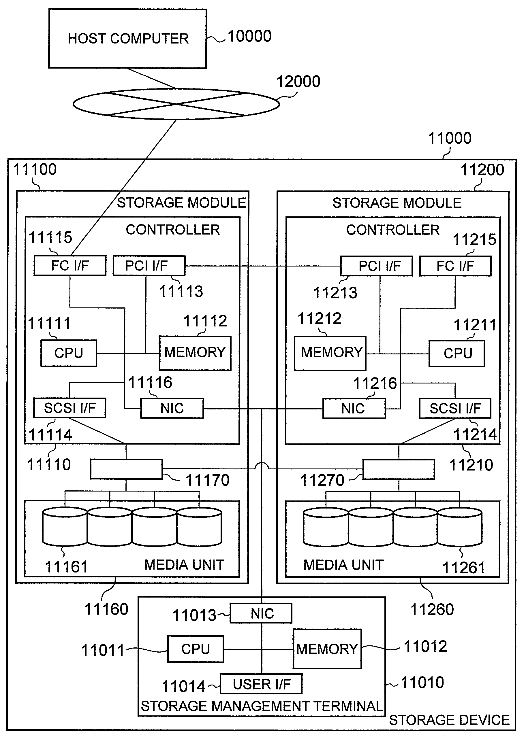
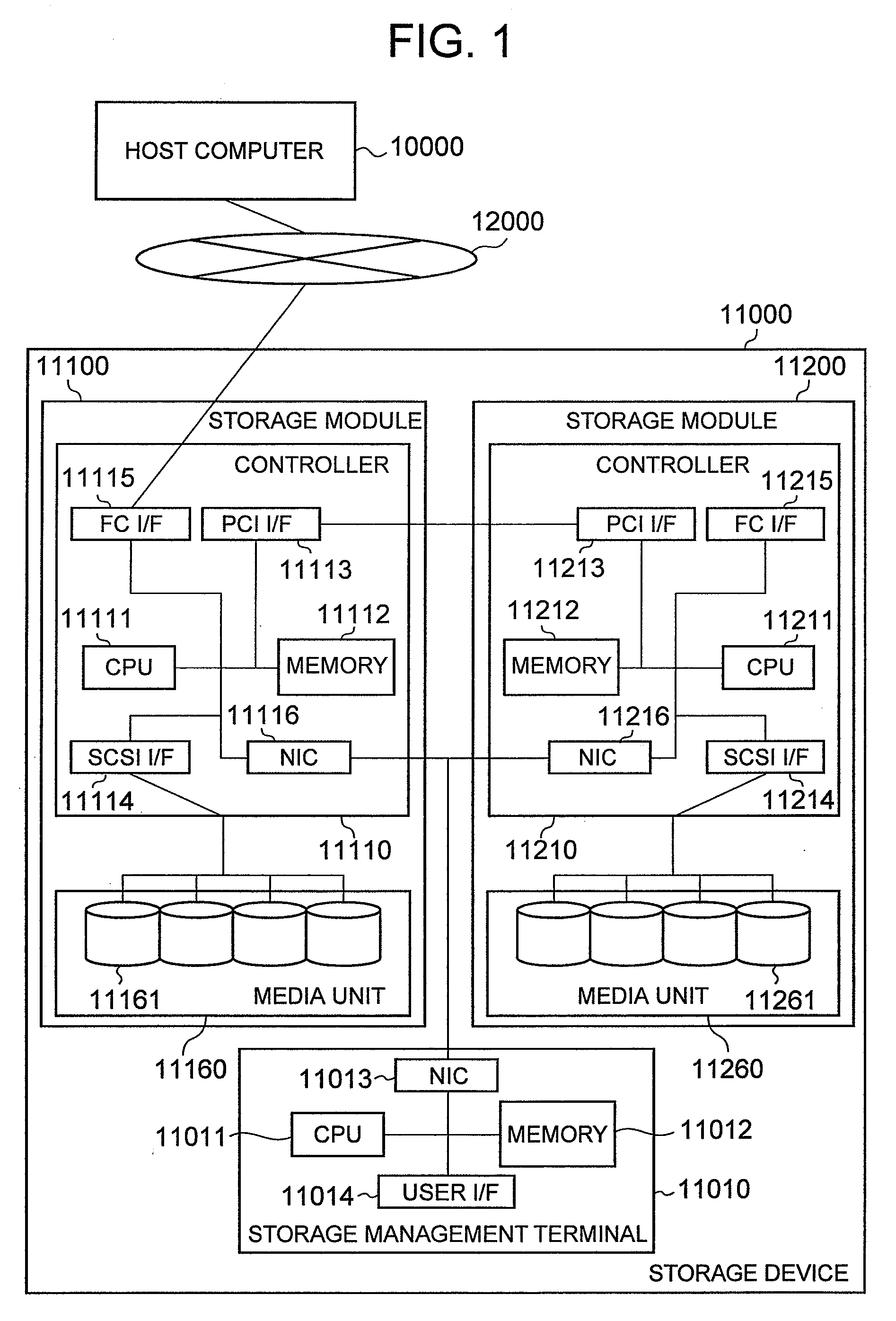
[0048]FIG. 1 is a diagram showing an example of the composition of a storage system according to a first embodiment of the present invention.

[0049]In this storage system, the storage device 11000 and the host computer 10000 are connected to a storage network 12000. The host computer 10000 sends a write request for writing data and a read request for reading out data, to the storage device 11000. The storage device 11000 comprises a storage module 11100 and a storage module 11200, which are examples of a storage module, and a storage management terminal 11010. The storage module 11100 and the storage module 11200 can be operated respectively and independently. In the present embodiment, the storage device 11000 comprises two storage modules, namely, a storage module 11100 and a storage module 11200, but the number of storage modules may be three or more.

[0050]The storage management terminal 11010 is a terminal for carrying out various management functions with respect to the storage ...

second embodiment

[0202]Next, the computer system according to a second embodiment of the present invention will be described. In the drawings and description of the second embodiment, elements which are the same as those of the first embodiment are labeled with the same reference numerals and the description below is centered on those features which are different from the first embodiment.

[0203]FIG. 31 is a diagram showing an example of the composition of a computer system according to a second embodiment of the present invention.

[0204]The storage module 11100 according to the second embodiment comprises a switch 11170, in addition to a media unit 11160 and a controller 11110. Furthermore, the storage module 11200 comprises a switch 11270, in addition to a media unit 11260 and a controller 11210.

[0205]The switch 11170 is connected to an HDD connection interface 11114 and to hard disk drives 111161. The switch 11260 is connected to an HDD connection interface 11214 and to hard disk drives 111161. Mor...


PUM


Abstract

The free region of a capacity pool is managed in a capacity pool structure management table stored in a memory, and if a capacity of a storage region that is to be assigned newly to a virtual volume by a processor is equal to or greater than a capacity of a free region of the capacity pool, or if the capacity of the free region of the capacity pool after assignment of a storage region to a virtual volume is less than a prescribed threshold value, then the data of at least any one virtual volume in the capacity pool, is migrated to another storage module, and the storage region of a HDD that was assigned to the virtual volume in question is added to the free capacity of the capacity pool, as a free region.

Description

CROSS-REFERENCE TO PRIOR APPLICATION[0001]This application relates to and claims the benefit of priority from Japanese Patent Application number 2007-18142, filed on Jan. 29, 2007 the entire disclosure of which is incorporated herein by reference.BACKGROUND OF THE INVENTION[0002]Conventionally, a method is commonly used in which a plurality of storage media are gathered in a storage device and are handled logically as one single storage volume, by integrated control of the plurality of storage media. By adopting a composition known as a RAID (Redundant Array of Inexpensive Disks) in a storage module of this kind, it has become possible to achieve high performance with parallel access, and high availability with data redundancy.[0003]In recent years, with the rise in the amounts of information being handled, the storage capacity required in storage devices has also increased. The following two technologies can be cited as examples of means for resolving this problem.[0004]The first t...

Claims


Application Information

Patent Timeline
Patent Type & Authority Applications(United States)
IPC IPC(8): G06F12/02G06F12/00
CPCG06F3/0608G06F3/0683G06F3/0665G06F3/0631
Inventor KAWAGUCHI, TOMOHIRO
Owner HITACHI LTD
Why Eureka
Try Eureka