Method for resizing pattern to be written by lithography technique, and charged particle beam writing method

Active Publication Date: 2008-07-31
NUFLARE TECH INC
View PDF9 Cites 11 Cited by
  • Summary
  • Abstract
  • Description
  • Claims
  • Application Information

AI Technical Summary

Benefits of technology

[0012]It is an object of the present invention to provide a highly precise method of resizing a pattern, with respect to a dimension change caused by a loading effect, and to provide an apparatus that writes a pattern using pattern data resized by the method.

Problems solved by technology

However, with an increase in miniaturization of a writing pattern, problems have occurred because of using a uniform correction amount (resizing amount) for all of a pattern.
Thus, when using a uniform resizing amount in a small region, the writing cannot be highly precisely executed because an over-corrected pattern is formed.

Method used


Image

  • Method for resizing pattern to be written by lithography technique, and charged particle beam writing method
  • Method for resizing pattern to be written by lithography technique, and charged particle beam writing method
  • Method for resizing pattern to be written by lithography technique, and charged particle beam writing method

Examples


embodiment 1

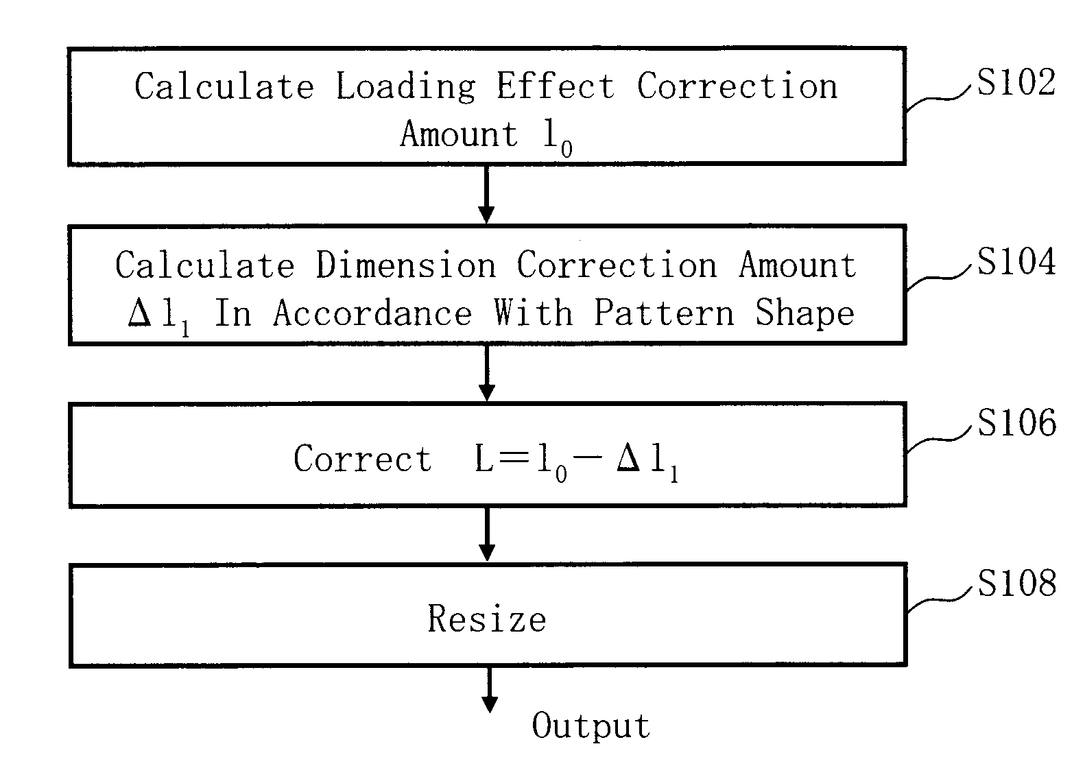
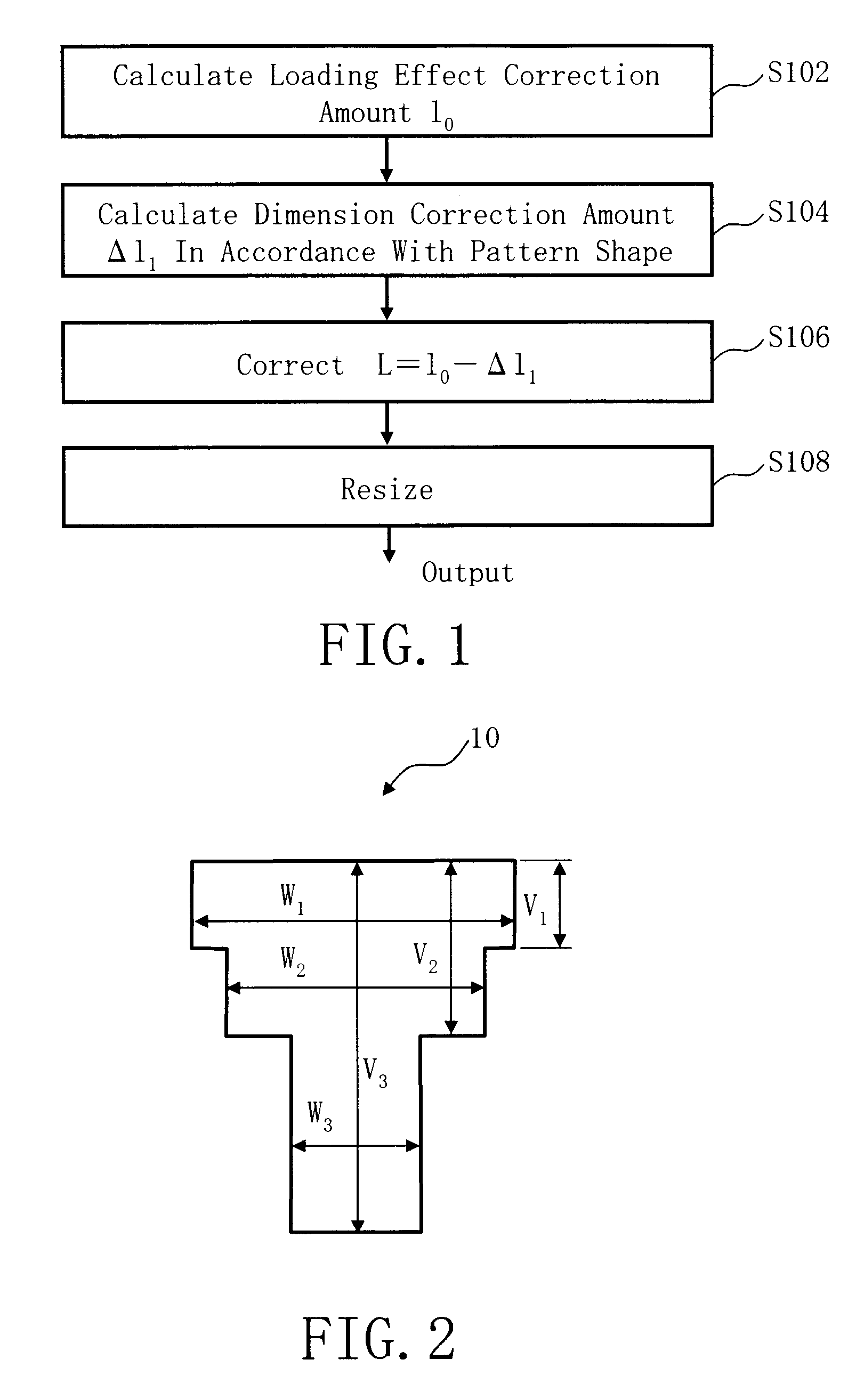
[0032]FIG. 1 is a flowchart showing main steps of a pattern resizing method described in Embodiment 1. In the figure, a series of steps as the resizing method of a writing pattern are executed as follows: a step of calculating a loading effect correction amount l0 (S102), a step of calculating a dimension correction amount Δl1 in accordance with a pattern shape (S104), a step of correcting the loading effect correction amount by using the dimension correction amount (S106), and a step of resizing (S108).

[0033]In S102, as a calculation step of a loading effect correction amount (an example of a first calculation step), a loading effect correction amount l0 (first dimension correction amount) of each small region is calculated. First, a writing region of a mask substrate being a target workpiece is virtually divided into meshes of a predetermined size. It is preferable to set the size to be approximately equal to or less than 1 / 10 of the influence range of the loading effect. For exam...

embodiment 2

[0044]In Embodiment 1, the resizing amount is corrected according to the shape of the pattern concerned. In Embodiment 2, the resizing amount is corrected according to the influence from a figure pattern located in the vicinity.

[0045]FIG. 5 is a flowchart showing main steps of a pattern resizing method described in Embodiment 2. In the figure, a series of steps as the resizing method of a pattern are executed as follows: a step of calculating a loading effect correction amount l0 (S102), a step of calculating a dimension correction amount Δl2 in accordance with the distance from an adjacent pattern and the shape of the adjacent pattern (S204), a step of correcting the loading effect correction amount by using the dimension correction amount (S206), and a step of resizing (S208).

[0046]Since the calculation step of the loading effect correction amount (S102) is the same as that of Embodiment 1, description thereof is omitted herein.

[0047]FIG. 6 shows an example of a pattern described ...

embodiment 3

[0058]In Embodiment 2, calculation is performed for each unit region dxdy and each result of the calculation is added, as integrated calculation. In Embodiment 3, there will be explained a method of correcting the influenced of the adjacent pattern by a simpler way though the precision may be decreased.

[0059]FIG. 9 is a flowchart showing main steps of a pattern resizing method described in Embodiment 3. In the figure, a series of steps as the resizing method of a pattern are executed as follows: a step of calculating a loading effect correction amount l0 (S102), a step of calculating a dimension correction amount Δl2′ in accordance with the distance between gravity centers of the pattern concerned and an adjacent pattern and the area of the adjacent pattern (S304), a step of correcting the loading effect correction amount by using the dimension correction amount (S306), and a step of resizing (S308).

[0060]Since the calculation step of the loading effect correction amount (S102) is t...


PUM


Abstract

A method for resizing a pattern to be written by using lithography technique includes calculating a first dimension correction amount of a pattern for correcting a dimension error caused by a loading effect, for each small region made by virtually dividing a writing region of a target workpiece into meshes of a predetermined size, based on an area density of the each small region, calculating a second dimension correction amount in accordance with a line width dimension of the pattern to be written in the each small region, correcting the first dimension correction amount by using the second dimension correction amount, and resizing the line width dimension of the pattern by using a corrected first dimension correction amount, and outputting a result of the resizing.

Description

CROSS-RELATION TO RELATED APPLICATION[0001]This application is based upon and claims the benefit of priority from the prior Japanese Patent Application No. 2006-249141 filed on Sep. 14, 2006 in Japan, the entire contents of which are incorporated herein by reference.BACKGROUND OF THE INVENTION[0002]1. Field of the Invention[0003]The present invention relates to a method for resizing a pattern to be written by lithography technique, and a charged particle beam writing method. More particularly, for example, the present invention relates to a method of previously resizing a pattern by using a dimension change amount of the pattern which is produced by a loading effect when performing a pattern forming after writing the pattern using electron beams, and to a writing method and apparatus for writing a pattern on a target workpiece based on resized pattern data using electron beams.[0004]2. Description of the Related Art[0005]Microlithography technology which forwards miniaturization of ...

Claims


Application Information

Patent Timeline
IPC IPC(8): G06F17/50
CPCB82Y10/00H01J37/3174H01J37/3026B82Y40/00
Inventor YASHIMA, JUNSUZUKI, JUNICHIABE, TAKAYUKI
Owner NUFLARE TECH INC
Why Eureka
Try Eureka