Ion spectrometric multipole rod systems made by wire erosion

a multi-pole rod and ion spectrometric technology, applied in the direction of manufacturing tools, welding equipment, arc welding equipment, etc., can solve the problems of unsatisfactory yield of successfully operating quadrupole filters, inability to adjust, and difficult manufacturing methods, etc., to achieve high-precision methods, fabricate precise and smooth surfaces, and facilitate processing

Inactive Publication Date: 2011-05-05
BRUKER DALTONIK GMBH
View PDF6 Cites 3 Cited by
  • Summary
  • Abstract
  • Description
  • Claims
  • Application Information

AI Technical Summary

Benefits of technology

[0012]By appropriate selection of the coefficients of expansion of the insulating rings and the metal pole rods, it is possible to ensure that the diagonal distance between the rod remains relatively constant even when temperatures vary.
[0013]The contacts of the pole rods, and in particular the interconnection of those pole rods that are joined to one phase of the RF voltage, can easily be applied prior to the wire erosion, for instance through spot welding. Mechanical distortion stresses that may be present in the metal as a result of preparatory working processes such as sawing, turning, drilling or spot welding can largely be annealed out by heat treatment prior to joining the metal to the insulators, so that the metal is not distorted through the relief of stress in the course of wire erosion. The wire erosion, which may take place in de-ionized water without creating additional mechanical or thermal stresses, does not introduce additional distortion stresses, in sharp contrast to machining by turning, milling or grinding. Residual mechanical distortion stresses can be relieved through a first, approximate wire erosion pass, known as roughing, prior to a second pass, the precision pass, that machines the final contours into the now relaxed metal.
[0014]Wire erosion, which is a modification of spark erosion, has now been developed into a highly precise method. It can be used to fabricate precise and smooth surfaces, particularly when these surfaces need to be parallel. The roughness is between about 0.05 and 0.5 micrometers. The dimensional accuracy of the surfaces lies in the range of about three micrometers, sometimes much closer, and can still be improved. The metal components can be manufactured from aluminum, stainless steel, brass or many other materials; aluminum is particularly easy to process. The inner surfaces of the multipole electrodes that face the axis can be given cylindrical or hyperbolic form through appropriate programming of the erosion machine.
[0015]The insulating rings or tubes can be made of glass, glass-ceramic (e.g., MACOR® machinable glass ceramic available from Corning), ceramic, plastic or even of metal with insulating layers of sufficient strength against disruptive electric discharges. Components or layers with a low tendency to shrink can be made from plastics with mineral fillers.

Problems solved by technology

This manufacturing method is difficult, and the resultant yield of successfully operating quadrupole filters has been unsatisfactory.
This method produces rigid, high-precision quadrupole rod systems which cannot be de-adjusted and are highly suitable for mass filters that can also be used under unfavorable environmental conditions, such as in vehicles.
Their mass range is, however, restricted to about m / z=1000 Dalton because leakage currents can occur at higher RF voltages.
This method of manufacture was not highly reproducible, and the ion guide systems made in this way are extremely sensitive to impacts and to bending forces; they are also sensitive to mechanical or acoustic vibrations, which can cause them to resonate.
In addition, they often tear off at the spot-welded attachment sites.
Slight deformations that result in irregular inside diameters can, however, significantly reduce the ion transmission or even entirely block it.
However, since the pole rods are only connected at one location to the outer metal ring, and this outer ring is joined via the insulating ring to the outer ring of the other multipole part, it is difficult to achieve precise assembly with accurately parallel alignment of all the pole faces to one another, and this cannot always be guaranteed.

Method used


Image

  • Ion spectrometric multipole rod systems made by wire erosion
  • Ion spectrometric multipole rod systems made by wire erosion
  • Ion spectrometric multipole rod systems made by wire erosion

Examples


Embodiment Construction

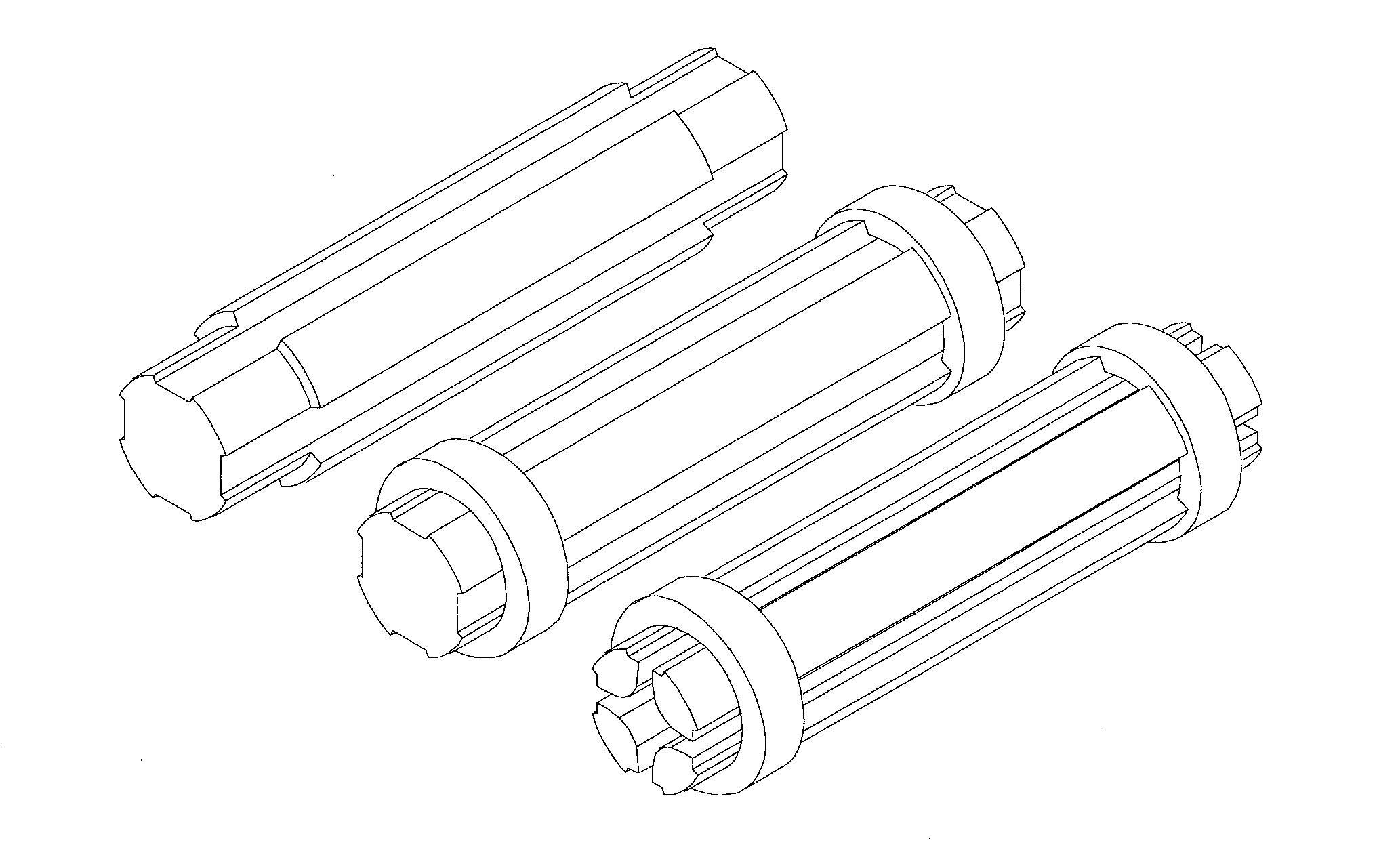
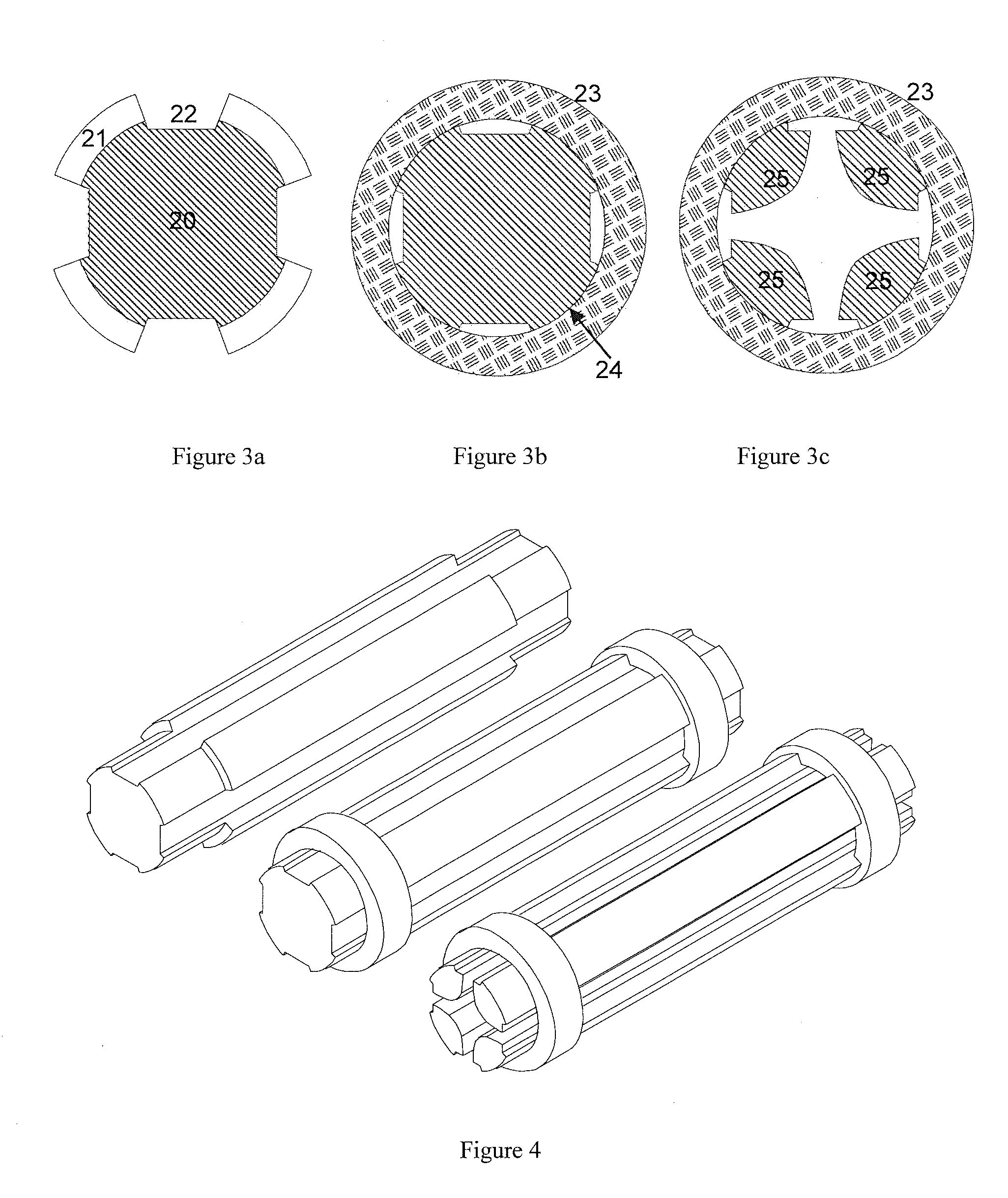
[0022]As described above, an aspect of the invention includes joining the metal parts for the multipole rod system and the matching insulating rings or tubes together to form an effectively inseparable block, for instance by gluing with an adhesive, soldering, brazing or riveting. Then pole rod contours facing are cut toward the axis by wire erosion. The cutting by wire erosion is preferably done for all the pole rods in a single pass, possibly after a preliminary “roughing pass”.

[0023]A method for manufacturing a multipole rod system thus may comprise providing insulating rings or tubes with mating faces for the pole rods, and providing one or more metal parts from which the multipole pole rods can be cut, having mating faces that match the mating faces of the insulating rings or tubes. The metal parts are bonded with the insulating rings or tubes to form a rigid unit, and then contours of the pole rods are cut by wire erosion.

[0024]It is possible, for instance, to braze individual...


PUM

PropertyMeasurementUnit
diametersaaaaaaaaaa
diametersaaaaaaaaaa
diametersaaaaaaaaaa

Abstract

A method for fabricating a multipole system from a composite, comprising metal and insulating components rigidly fastened together, includes spark erosion cutting with a moving wire cathode to create a solid block whose metal pole faces are accurately parallel to one another.

Description

PRIORITY INFORMATION[0001]This patent application claims priority from German Patent Application No. 10 2009 051 891.6 filed on Nov. 4, 2009, which is hereby incorporated by reference.FIELD OF INVENTION[0002]The invention relates to a method for manufacturing precision multipole rod systems that can be supplied with RF voltages for use as ion guide systems with collision focusing, mass-selective quadrupole filters or cells for collision-induced fragmentation in mass or ion mobility spectrometers.BACKGROUND OF THE INVENTION[0003]A variety of methods are known for the manufacture of multipole rod systems. Precisely honed round rods, fastened to suitably ground ceramic rings usually by screws, were often used for quadrupole rod systems intended for analytic use. This manufacturing method is difficult, and the resultant yield of successfully operating quadrupole filters has been unsatisfactory. Later, hyperbolically ground metal rods were used, screwed into precisely fabricated glass ca...

Claims


Application Information

Patent Timeline
Patent Type & Authority Applications(United States)
IPC IPC(8): B23H1/00
CPCB23H9/00B23H7/02
Inventor REBETTGE, JENS
Owner BRUKER DALTONIK GMBH
Why Eureka
Try Eureka