Method for resizing pattern to be written by lithography technique, and charged particle beam writing method
a technology of lithography and pattern, applied in the field of lithography pattern resizing and pattern writing by lithography technique, can solve the problems of inability to write highly precisely, and the writing has not yet been fully executed
- Summary
- Abstract
- Description
- Claims
- Application Information
AI Technical Summary
Benefits of technology
Problems solved by technology
Method used
Image
Examples
embodiment 1
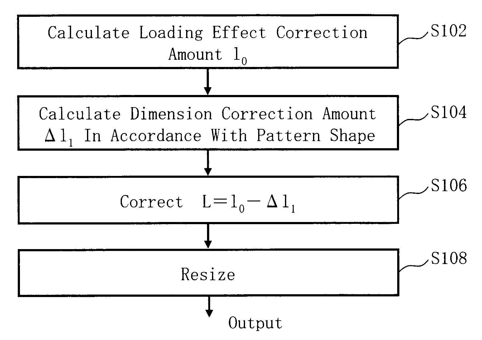
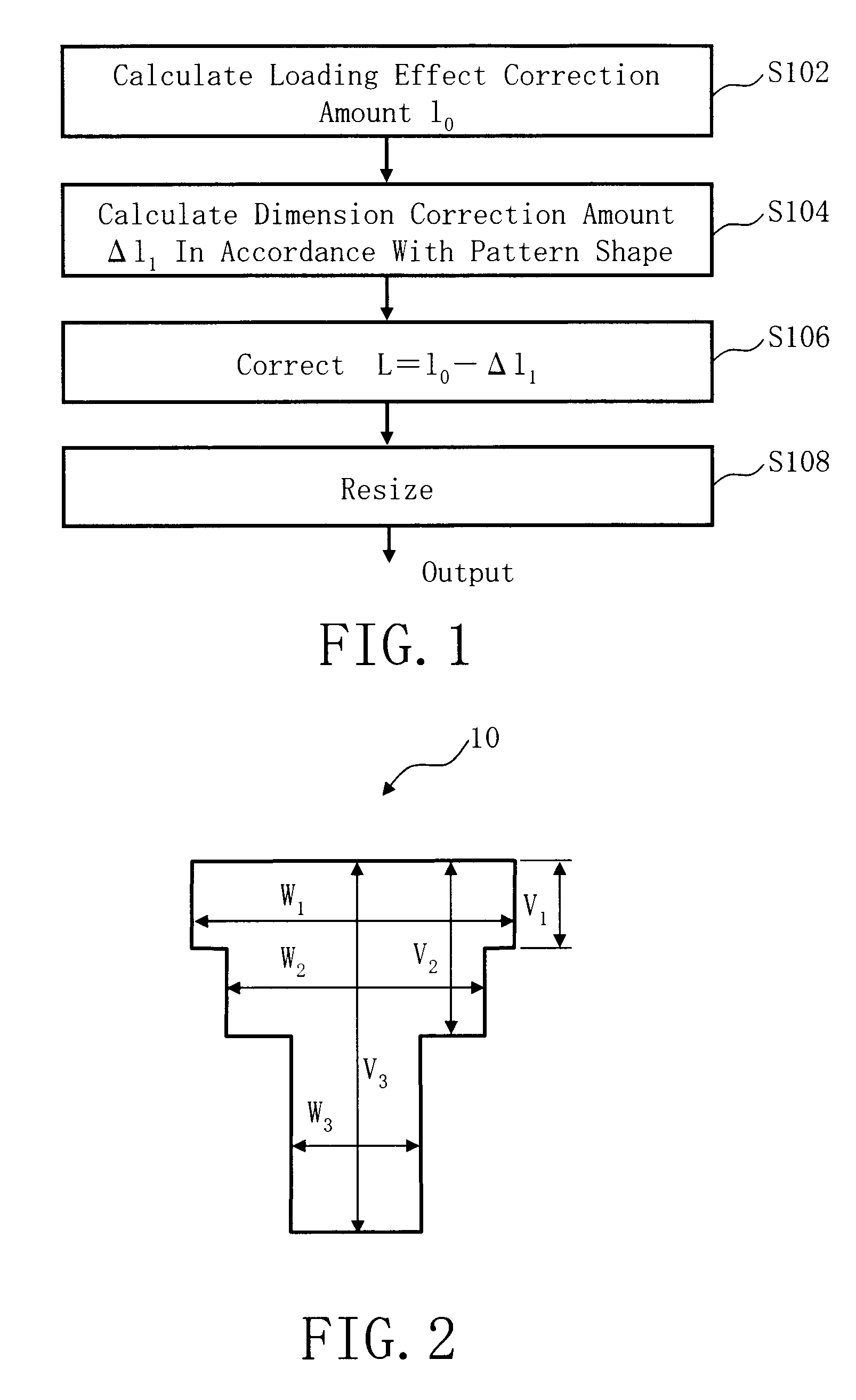
[0032]FIG. 1 is a flowchart showing main steps of a pattern resizing method described in Embodiment 1. In the figure, a series of steps as the resizing method of a writing pattern are executed as follows: a step of calculating a loading effect correction amount l0 (S102), a step of calculating a dimension correction amount Δl1 in accordance with a pattern shape (S104), a step of correcting the loading effect correction amount by using the dimension correction amount (S106), and a step of resizing (S108).
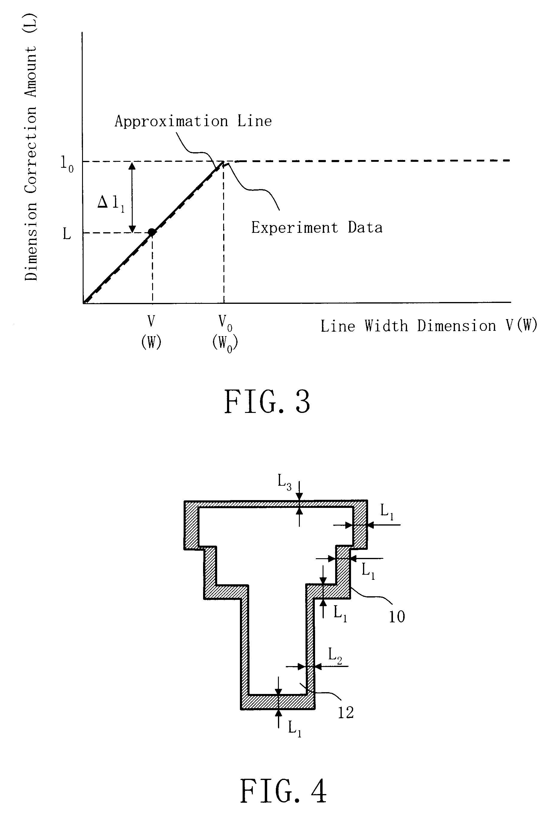
[0033]In S102, as a calculation step of a loading effect correction amount (an example of a first calculation step), a loading effect correction amount l0 (first dimension correction amount) of each small region is calculated. First, a writing region of a mask substrate being a target workpiece is virtually divided into meshes of a predetermined size. It is preferable to set the size to be approximately equal to or less than 1 / 10 of the influence range of the loading effect. For exam...
embodiment 2
[0044]In Embodiment 1, the resizing amount is corrected according to the shape of the pattern concerned. In Embodiment 2, the resizing amount is corrected according to the influence from a figure pattern located in the vicinity.
[0045]FIG. 5 is a flowchart showing main steps of a pattern resizing method described in Embodiment 2. In the figure, a series of steps as the resizing method of a pattern are executed as follows: a step of calculating a loading effect correction amount l0 (S102), a step of calculating a dimension correction amount Δl2 in accordance with the distance from an adjacent pattern and the shape of the adjacent pattern (S204), a step of correcting the loading effect correction amount by using the dimension correction amount (S206), and a step of resizing (S208).
[0046]Since the calculation step of the loading effect correction amount (S102) is the same as that of Embodiment 1, description thereof is omitted herein.
[0047]FIG. 6 shows an example of a pattern described ...
embodiment 3
[0060]In Embodiment 2, calculation is performed for each unit region dxdy and each result of the calculation is added, as integrated calculation. In Embodiment 3, there will be explained a method of correcting the influenced of the adjacent pattern by a simpler way though the precision may be decreased.
[0061]FIG. 9 is a flowchart showing main steps of a pattern resizing method described in Embodiment 3. In the figure, a series of steps as the resizing method of a pattern are executed as follows: a step of calculating a loading effect correction amount l0 (S102), a step of calculating a dimension correction amount Δl2′ in accordance with the distance between gravity centers of the pattern concerned and an adjacent pattern and the area of the adjacent pattern (S304), a step of correcting the loading effect correction amount by using the dimension correction amount (S306), and a step of resizing (S308).
[0062]Since the calculation step of the loading effect correction amount (S102) is t...
PUM
 Abstract
Description
Claims
Application Information
 - R&D
- Intellectual Property
- Life Sciences
- Materials
- Tech Scout
- Unparalleled Data Quality
- Higher Quality Content
- 60% Fewer Hallucinations
Browse by: Latest US Patents, China's latest patents, Technical Efficacy Thesaurus, Application Domain, Technology Topic, Popular Technical Reports.
© 2025 PatSnap. All rights reserved.Legal|Privacy policy|Modern Slavery Act Transparency Statement|Sitemap|About US| Contact US: help@patsnap.com


