
Mount structure for sensor device

a sensor device and mounting structure technology, applied in the direction of bumpers, using reradiation, instruments, etc., can solve the problems of processing circuit malfunction, sensor device damage, sensing element misalignment or detachment,

Inactive Publication Date: 2008-08-07
DENSO CORP
View PDF3 Cites 40 Cited by
  • Summary
  • Abstract
  • Description
  • Claims
  • Application Information

AI Technical Summary

Benefits of technology

[0010]To achieve the objective of the present invention, there is also provided a mount structure for a mobile unit, the mount structure including a sensor device and a color film. The sensor device is mounted on a wall member of the mobile unit via a through hole of the wall member such that a sensing element of the sensor device is able to perform sensing. The sensor device is coupled to the wall member in a state, where the sensor device has a portion that is generally flush with an outer surface of the wall member, and that is provided inside the through hole. The color film is adhered to an entire surface of the outer surface of the wall member. The entire surface has an opening of the through hole. The sensor device contacts the color film.

Problems solved by technology

Thus, the sensor device is held in the high temperature atmosphere, and thereby the sensor device may be damaged.
For example, adhesive for fixing the sensing element may be influenced by the heat, and as a result, the sensing element may be misaligned or detached.
Also, a processing circuit of the sensing element may be influenced by the heat, and as a result, the processing circuit may malfunction.

Method used


Image

  • Mount structure for sensor device
  • Mount structure for sensor device
  • Mount structure for sensor device

Examples


first embodiment

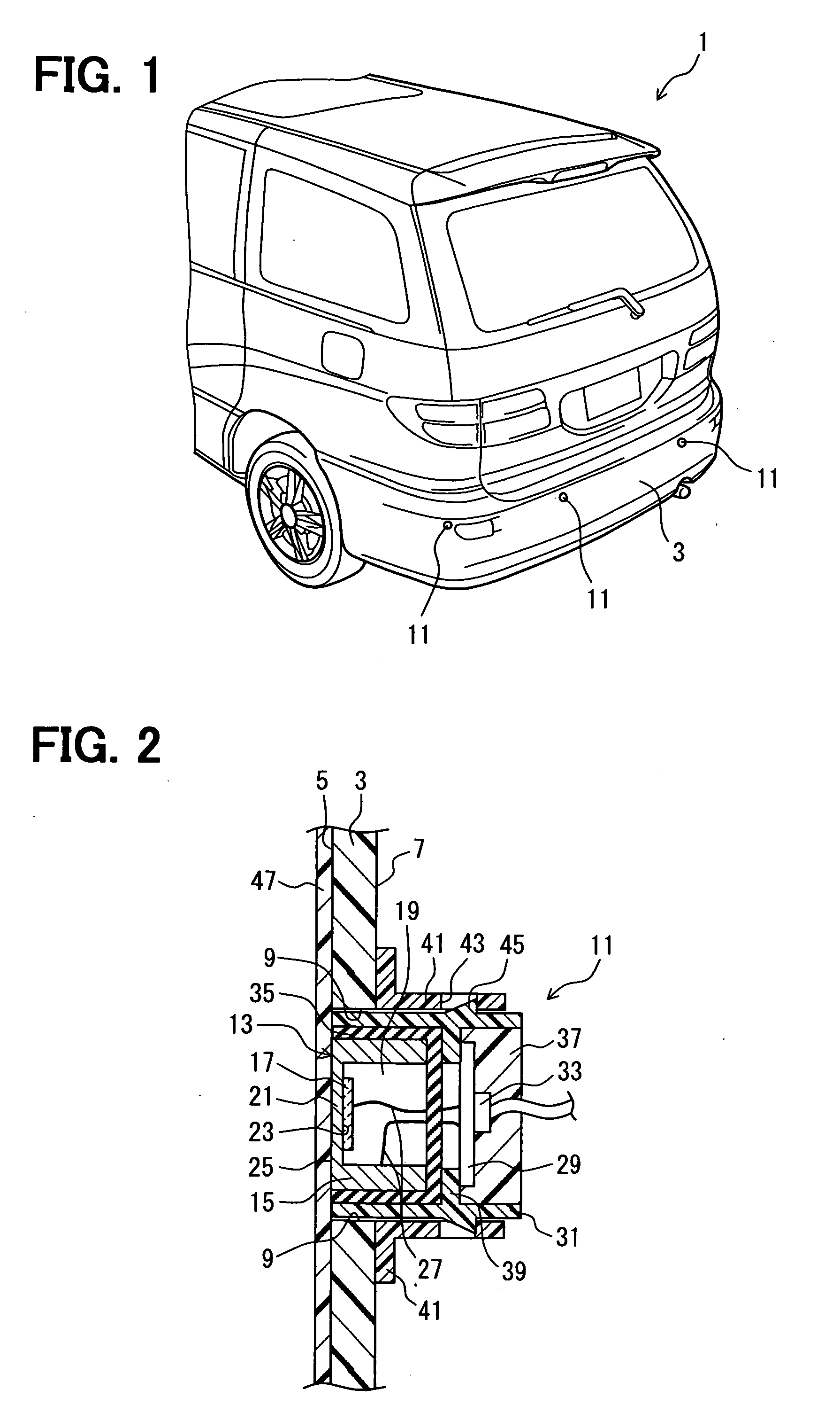
[0023]A sensor device is designed to detect an obstacle around a vehicle, and is mounted either on a front side of a vehicle, on a rear side of the vehicle, or on four corners of the vehicle on bumpers. In the present embodiment, as shown in FIG. 1, sensor devices 11 are mounted on four positions of a vehicle 1, typically, on opposite corners of a rear bumper 3 and on two positions between the corners.

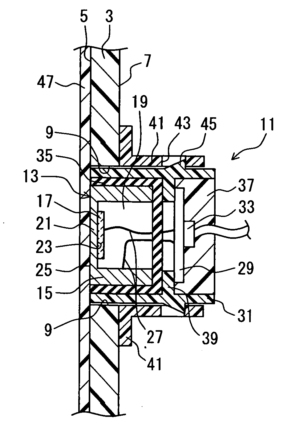
[0024]As shown in FIG. 2, the sensor device 11 includes an ultrasonic transducer 13 (i.e., a microphone) as a main part. The ultrasonic transducer 13 has a housing 15 and a piezoelectric element 17, which is received by the housing 15. The housing 15 corresponds to an enclosure of the present invention, and is typically made of an electrically conductive member to have a hollow cylinder having a bottom. The electrically conductive member may be aluminum, for example. Alternatively, the housing 15 may be made of a resin material and has an metallized inner surface. The housing 15 has an...

second embodiment

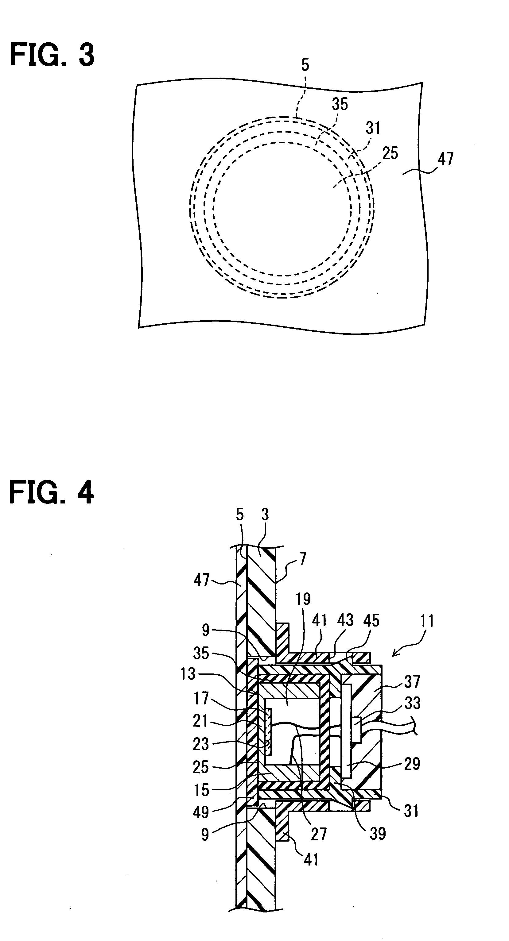
[0040]The second embodiment of the present invention will be described with reference to FIG. 4 and FIG. 5.

[0041]A mount structure for a sensor device according to the second embodiment has similar components and structures similar to those of the first embodiment. Thus, explanation of the similar components and structures is omitted and parts different from the first embodiment will be mainly described. Note that the similar components similar to those described in the first embodiment are indicated by the same numerals.

[0042]In a structure, where a piezoelectric element senses through a bumper (e.g., invisible sonar), the bumper may influence the sensing ability. In the first embodiment, the vibration plane 25 of the ultrasonic transducer 13 directly contacts the color film 47 in order to limit the influence by the bumper 3 on the sensitivity and to improve the design. In practice, the color film 47 is focusing more on improving the design. Thus, in the present embodiment, as show...


PUM


Abstract

A mount structure for a mobile unit includes a wall member, a sensor device, and a color film. The wall member is provided to the mobile unit, and the wall member has a through hole and an outer surface. The sensor device is mounted on the wall member via the through hole such that a sensing element of the sensor device is able to perform sensing. The sensor device is coupled to the wall member in a state, where the sensor device has a portion that is generally flush with the outer surface of the wall member, and that is provided inside the through hole. The color film is adhered to an entire surface of the outer surface of the wall member, and the entire surface has an opening of the through hole. The sensor device contacts the color film.

Description

CROSS REFERENCE TO RELATED APPLICATION[0001]This application is based on and incorporates herein by reference Japanese Patent Application No. 2007-25943 filed on Feb. 5, 2007.BACKGROUND OF THE INVENTION[0002]1. Field of the Invention[0003]The present invention relates to a mount structure for a sensor device, which structure mounts the sensor device on a wall member of a mobile unit, such as a vehicle bumper.[0004]2. Description of Related Art[0005]Conventionally, there is known a mount structure for a sensor device, in which structure a wall member (e.g., a vehicle bumper) of a mobile unit has a through hole, and the sensor device is mounted on the wall member through the through hole such that a sensing element can sense an object (see, for example, JP-A-2004-264264).[0006]In JP-A-2004-264264, a bumper (wall member) has a mounting hole (through hole) that extends through the bumper from one surface to an opposite surface, and a sensor device has a housing (enclosure) that receives...

Claims


Application Information

Patent Timeline
IPC IPC(8): G12B9/08G01D11/30H05K7/14G01S15/93G12B9/02G01D11/24
CPCG01S7/521G10K11/004G10K9/122G01S2015/938B60R19/48G01S15/93
Inventor SATO, YOSHIHISA
Owner DENSO CORP
Learn More