Press key structure

a key and key technology, applied in the direction of contact mechanisms, electrical devices, electric switches, etc., can solve the problems of poor contact between the conducting panel and the circuit board, poor yield, increased manufacturing costs, etc., and achieve the effect of preventing the sam

Inactive Publication Date: 2008-08-07
DARFON ELECTRONICS CORP
View PDF11 Cites 17 Cited by
  • Summary
  • Abstract
  • Description
  • Claims
  • Application Information

AI Technical Summary

Benefits of technology

[0004]In view of the disadvantages of prior art, the primary object of the present invention is to provide a press key structure capable of providing a uniform support to its keycap for preventing the same from slanting by pressing that is especially suitable for a press key with bar-shaped keypad.

Problems solved by technology

Consequently, the conducting plate arranged at the bottom of the elastic member 15 will not be able to have an exact contact with the circuit board 16 disposed beneath the substrate 14, that is, the contact between the conducting panel and the circuit board is poor.
However, when a key cap is integrally formed with a poorly designed reinforcement structure or with a thick reinforcement structure, such keycap consequently is going to surfer for having a shrinking pressing surface that no only it is not good looking, but also the yield is poor.
Moreover, as such reinforcement structure is disposed beneath the keycap, its disposition is restricted by those other structures formed under the keycap in a manner that it is unable to evenly distribute the pressing force over the entire surface of the keycap; and as the structure of such enforcement rib is comparatively complex, the manufacturing cost is increased.

Method used


Image

  • Press key structure
  • Press key structure
  • Press key structure

Examples


Embodiment Construction

[0028]For your esteemed members of reviewing committee to further understand and recognize the fulfilled functions and structural characteristics of the invention, several exemplary embodiments cooperating with detailed description are presented as the follows.

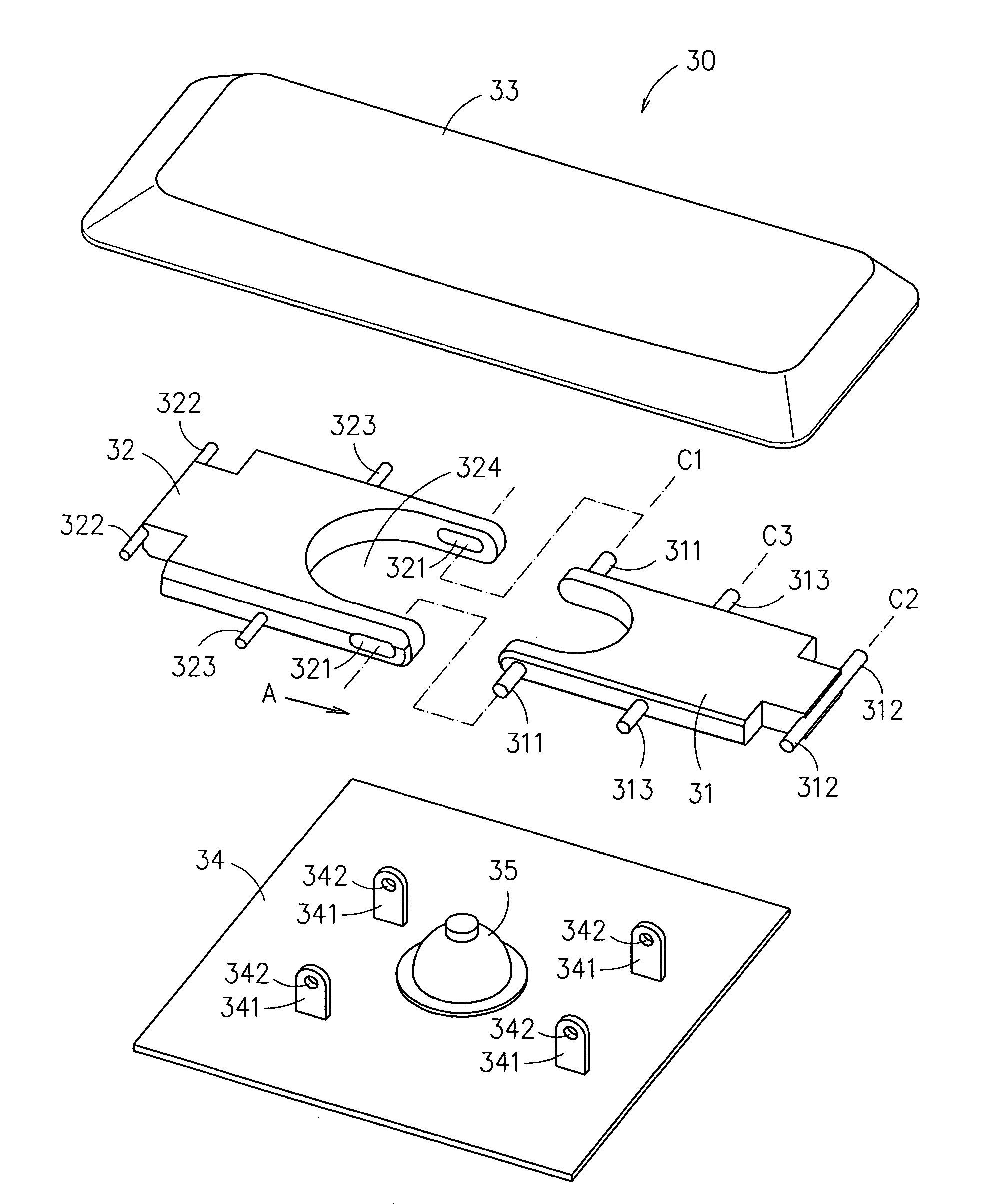
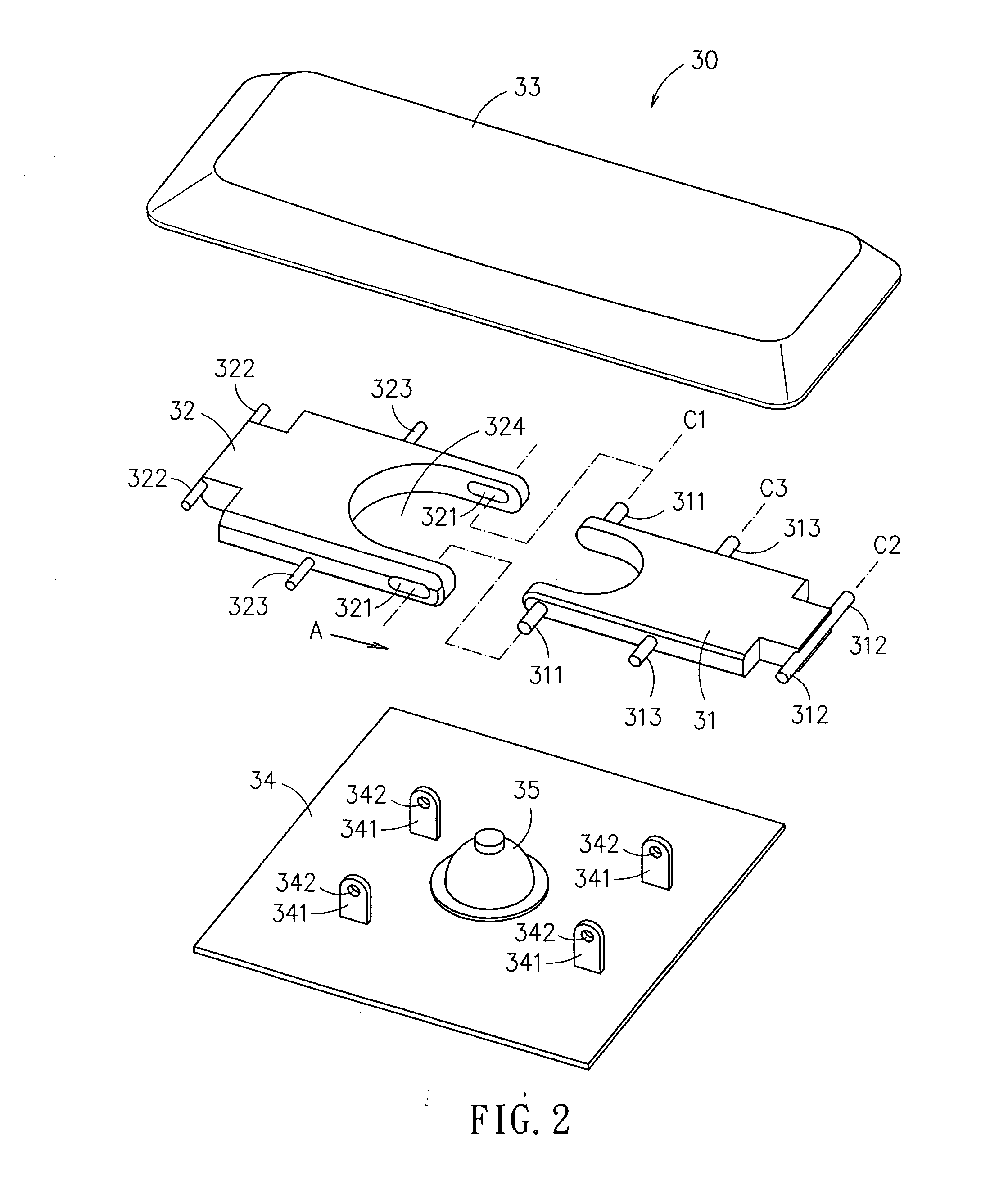
[0029]Please refer to FIG. 2 and FIG. 3, which show a press key structure according to an exemplary embodiment of the invention. The press key structure 30 in the embodiment comprises: a keycap 33, a substrate 34, and first movable panel 31 and a second movable panel 32. The keycap 33 is configured with a bottom surface while arranged the substrate 34 beneath the keycap 33 forming a space sandwiched therebetween for receiving the first and the second movable panels 31, 32 therein. The press key structure 30 further comprises an elastic member 35, which is disposed on the substrate 34 at position corresponding to the bottom surface of the keycap 33 in a manner that the elastic member 35 is deformed when the keycap 33 is subject...


PUM


Abstract

A press key structure is disclosed, which comprises: a keycap, configured with a bottom surface; a substrate; a first movable panel; and a second movable panel; wherein the substrate is arranged at a position underneath the keycap while disposing the first and the second movable panels in a space sandwiched between the substrate and the keycap and pivotally coupling the two by the use of a flange and a groove formed respectively on the two neighboring edges of the first and the second movable panels in a manner that the flange is slidably inset into the groove; and the each of the first and the second movable panels is coupled to the substrate by the center thereof while enabling the two edges of the first and the second movable panels that are away from each other to pivotally coupled to the bottom surface of the keycap. With the aforesaid structure, a first angle is included between the first and the second movable panels when the keycap is not pressed by a force; and a second angle that is larger than the first angle is included between the first and the second movable panels when the keycap is pressed.

Description

FIELD OF THE INVENTION [0001]The present invention relates to an improved press key structure, and more particularly, to a press key structure capable of providing a uniform support to its keycap for preventing the same from slanting by pressing that is especially suitable for a press key with bar-shaped keypad.BACKGROUND OF THE INVENTION [0002]Conventionally, a press key 10 is usually constructed with a scissors-type elastic structure as shown in FIG. 1, which comprises: a keycap 13, a substrate 14 and two supporting arms 11, 12 sandwiched between the keycap 13 and the substrate 14. In FIG. 1, the two supporting arms 11, 12 are pivotally coupled with each other at the middle thereof forming an X-shaped structure. Such conventional scissors-type press key 10 is favored for its longer stroke and lower noise, etc., so that it is vastly adopted by those thin-type keyboards in recent year, especially for keyboards of notebook computers. However, such scissors-type press key 10 still has...

Claims


Application Information

Patent Timeline
Patent Type & Authority Applications(United States)
IPC IPC(8): H01H13/26
CPCH01H3/125
Inventor LIN, CHING-TING
Owner DARFON ELECTRONICS CORP
Why Eureka
Try Eureka