Flow-regulating valve and oil level control system using same

a technology of flow-regulating valves and oil level control systems, applied in the direction of valve details, valve arrangements, multiple-way valves, etc., can solve the problems of pump suction loss and air entering the transmission fluid circuit, and achieve the effect of opening or closing more quickly

Inactive Publication Date: 2008-08-07
GM GLOBAL TECH OPERATIONS LLC
View PDF4 Cites 23 Cited by
  • Summary
  • Abstract
  • Description
  • Claims
  • Application Information

AI Technical Summary

Benefits of technology

[0004]A flow-regulating valve is provided that uses at least one active material component that may be activated to actuate the active material component (i.e., change some dimensional characteristic of the active material component) to control fluid flow through the valve. The active material component is activated passively, preferably by the surrounding ambient temperature, and actuates over a period of time beginning at a predetermined transformation temperature to control movement of one or more members of the valve and thus the alignment of openings in the members to control fluid flow through the valve. Preferably, several moveable members are arranged to provide movement in a telescoping manner with respect to one another in response to the passive activation of respective active material components connected with the movable members. Additionally, an actuator, which may be of any type, such as a solenoid or even another active material component, is actively actuated, such as through resistive heating, for instance in the case of using a smart material actuator, in response to a control signal, to provide an active level of control of fluid flow through the valve. The resistive heating may be in response to a control signal, for instance, in the case where the active material component is a smart material actuator. Active activation allows a more fine-tuned control of valve actuation speed than if valve actuation were based on passive activation alone and also allows the state of a set or sets of active material components to be changed to a state different from that at ambient. For example, active activation via a control signal from a controller allows the valve to open or close more quickly in response to one or more predetermined conditions than it would based on the passive activation (e.g., due to a change in surrounding temperature) alone.

Problems solved by technology

For instance, the predetermined condition may be high g-forces during turning of a vehicle, causing the fluid in the bottom pan to be moved away from the pump inlet, thereby causing the pump to lose suction and get air into the transmission fluid circuit.

Method used


Image

  • Flow-regulating valve and oil level control system using same
  • Flow-regulating valve and oil level control system using same
  • Flow-regulating valve and oil level control system using same

Examples


first embodiment

of a Flow-Regulating Valve

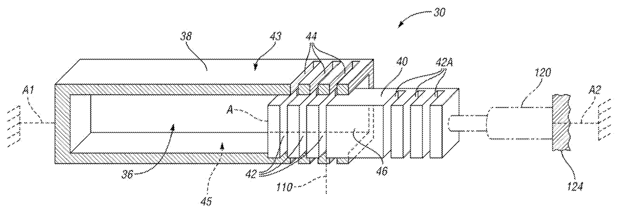
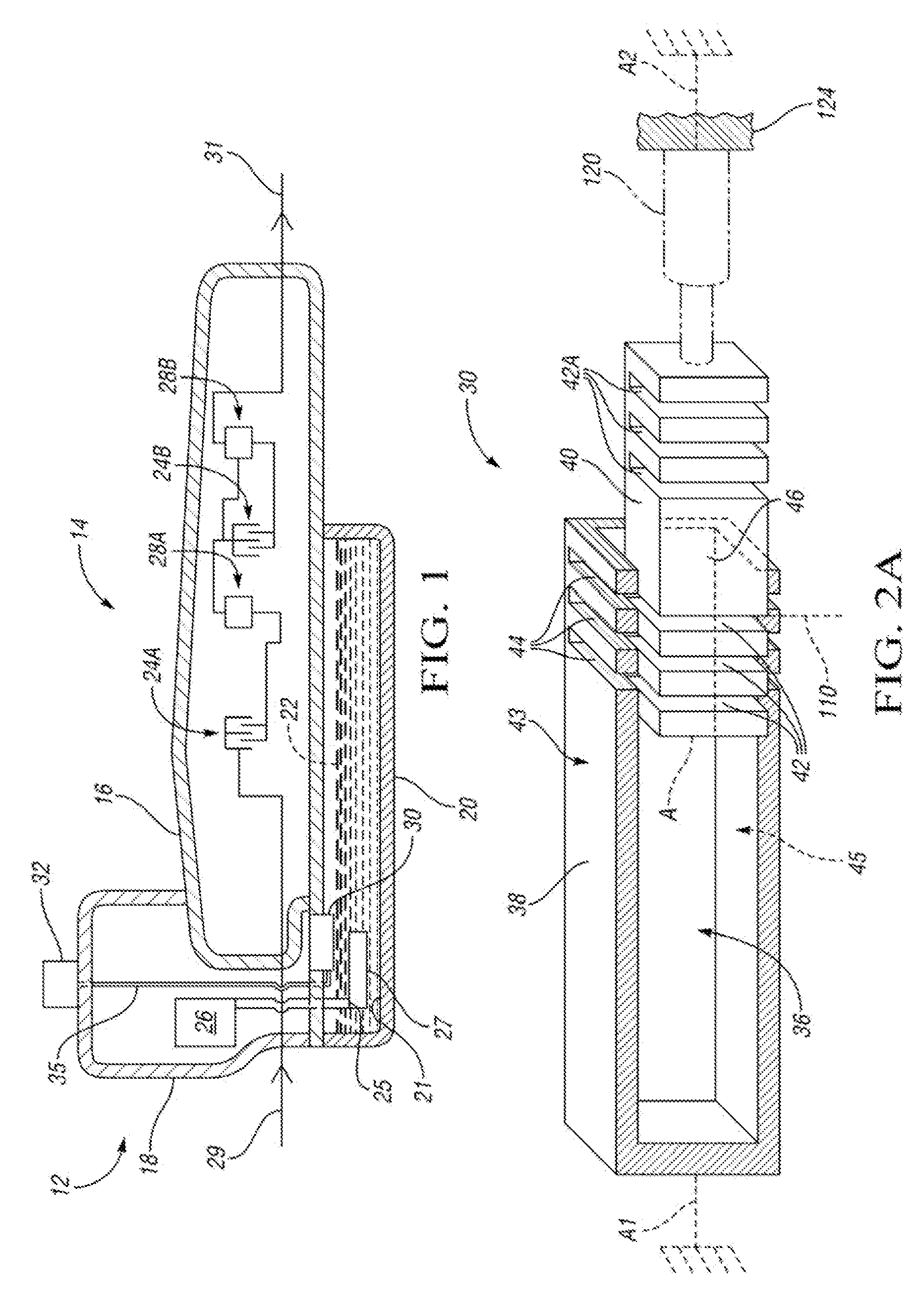
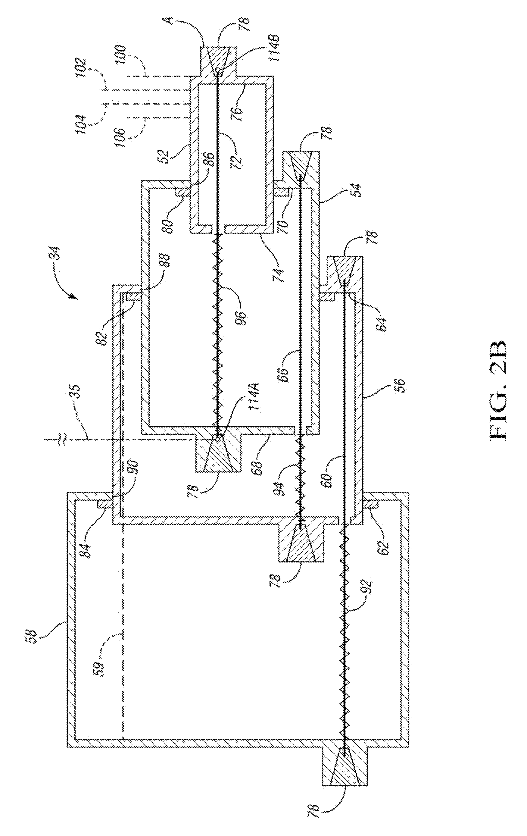
[0021]Referring to FIGS. 2A and 2B, a first embodiment of the flow-regulating valve 30 is shown. The portion of the flow-regulating valve 30 shown in FIG. 2B is a telescoping active material actuator portion 34 that connects with the portion shown in FIG. 2A at the surface labeled A in both FIGS. 2A and 2B, with the telescoping actuator portion 34 preferably sized to fit within the cavity 36 formed within a fixed member 38 (also referred to herein as the second member).

[0022]Referring to FIG. 2A, the valve 30 includes a first, movable member 40 that is positioned for telescoping movement within the second, fixed member 38 due to actuation of the telescoping active material actuator portion 34. The fixed member 38 has a hollow rectangular shape and the movable member 40 has a solid rectangular shape sized to fit within the hollow portion of the fixed member 38. Within the scope of the invention, the fixed member 38 and movable member 40 may have many other c...

second embodiment

of a Flow-Regulating Valve

[0057]A second embodiment of a flow-regulating valve within the scope of the invention includes the first and second members 38 and 40 of FIG. 2A with respective openings 44, 42, 42A, as well as the telescoping active material actuator portion 34 of FIG. 2B. However, the active material component 72 is passively activated by surrounding temperature in this embodiment (rather than by resistive heating) and the activation of the three active material components 60, 66 and 72 only move first member 40 to the blocking position in which solid portion 46 of first member 40 aligns with openings 44 in fixed second member 38 to prevent fluid flow through flow-regulating valve 30. When a predetermined condition occurs, such as a high acceleration turn, a solenoid 120, rather than an active material component, acts as an actuator, and is controlled via an electronic control signal from controller 32 to push the first member 40 so that openings 42A align with openings ...

third embodiment

of a Flow-Regulating Valve

[0058]Referring to FIG. 3, another embodiment of a flow-regulating valve 230 allows the active material actuator portion 34 of FIG. 2B to be packaged remotely from the first movable member 240 and second fixed member 238 by utilizing a connector 242 between the first movable member 240 and the active material actuator assembly portion 34, which has surfaces A in FIG. 2B connected at end AA of the connector 242. Accordingly, more flexibility in sizing of the active material actuator portion 34 is available, as it need not fit within a cavity in the fixed second member 238 as it had to fit within fixed second member 38 in the embodiment of FIG. 2B. The passive activation of the active material components 60, 66 and the active actuation of active material component 72 (i.e., the actuator) functions the same as described with respect to the first embodiment. Respective openings shown in the first member 240 and second member 238 align and misalign in response t...


PUM


Abstract

A flow-regulating valve has at least one active material component that may be passively activated (e.g., in response to changes in surrounding temperature) to control fluid flow through the valve. Additionally, an actuator, which may be of any type, such as a solenoid or even another active material component, actuates due to active activation, such as resistive heating in response to a sensor/control signal, which could be due to external conditions (such as existence of high acceleration) or internal conditions (such as change in fluid temperature) to provide an active level of control of fluid flow through the valve. The flow-regulating valve may be used in an oil level control system of a transmission to ensure adequate oil availability during various operating conditions while minimizing the adverse effects such as spin and windage losses. Similar applications can be made in other fluid flow or fluid level control systems.

Description

TECHNICAL FIELD[0001]The invention relates to a flow-regulating valve and an oil level control system for a transmission having the flow-regulating valve.BACKGROUND OF THE INVENTION[0002]Many applications requiring regulated fluid flow utilize valves that open different amounts in response to one or multiple factors. Such a valve may be actively controlled via an electronic controller. Alternatively, passive control is sometimes possible, such as with a valve having a thermostatic element that varies its opening with changes in fluid temperature.[0003]One application that has utilized flow control valves is a vehicle transmission. Vehicle transmissions typically have rotating parts that require constant lubrication. A certain level of fluid is required to be maintained in the transaxle in order to ensure a proper operation of its hydraulic system. The fluid circuit often includes one or more pumps located within the side cover attached to a main housing with a suction inlet coming f...

Claims


Application Information

Patent Timeline
Patent Type & Authority Applications(United States)
IPC IPC(8): F16K31/64
CPCF16H57/0435F16H57/0443F16K31/025F16K11/20F16K31/002F16H57/0447
Inventor UKPAI, UKPAI I.BUCKNOR, NORMAN K.
Owner GM GLOBAL TECH OPERATIONS LLC
Why Eureka
Try Eureka