Sprung support, particularly for a mattress

a spring base and mattress technology, applied in the field of spring base, can solve the problems of production cost differences between the known supportive spring bases, and achieve the effects of avoiding local indentations, avoiding snapping connections, and large surface area

Inactive Publication Date: 2008-08-07
THOMAS TECHN INNOVATION
View PDF4 Cites 7 Cited by
  • Summary
  • Abstract
  • Description
  • Claims
  • Application Information

AI Technical Summary

Benefits of technology

[0009]Provision is furthermore made for the connecting elements to be of at least partially elastic design. If they are not elastic, rigid or quasi-rigid properties are obtained. Connecting elements comprising flexurally slack ropes or straps were only suitable for transmitting tensile forces between adjacent spring slats; by contrast, it is possible for the connecting elements according to the invention, on account of them being of elastic design, to transmit at least part of the movement of the particular spring slat to at least one adjacent spring slat. In particular, the elastic properties of the connecting elements make it possible, at least in part, to transmit a vertical movement of a particular spring slat to at least one adjacent spring slat in such a manner that the latter likewise executes a vertical movement. The connecting elements therefore provide a comprehensive intercoupling of the spring slats by a type of bridge formation. The consequence is that not only do individual spring slats change their shape when subjected to a load, in particular sag, which could result in a discontinuous profile for the supportive spring base, but also, the coupling together of the spring slats by means of the connecting elements, which are of elastic design according to the invention, results in the sagging of individual spring slats being transmitted to the other spring slats, as a result of which the supportive spring base undergoes a continuous, steady change in shape. A “sliding” transition between adjacent spring slats may also be spoken of.
[0024]Furthermore, the use of the elastic net or else of the connecting elements of defined elasticity makes it possible to design the supportive spring base in a manner such that it can be rolled up and therefore transported in a space-saving manner. The elastic properties of the net or of the other connecting elements which are not net-like not only permit the supportive spring base according to the invention to be rolled up in a simple and space-saving manner; what is more, the supportive spring base inevitable returns into its planar position after being unrolled.

Problems solved by technology

Further differences between the known supportive spring bases are found in their production costs.

Method used


Image

  • Sprung support, particularly for a mattress
  • Sprung support, particularly for a mattress
  • Sprung support, particularly for a mattress

Examples


Embodiment Construction

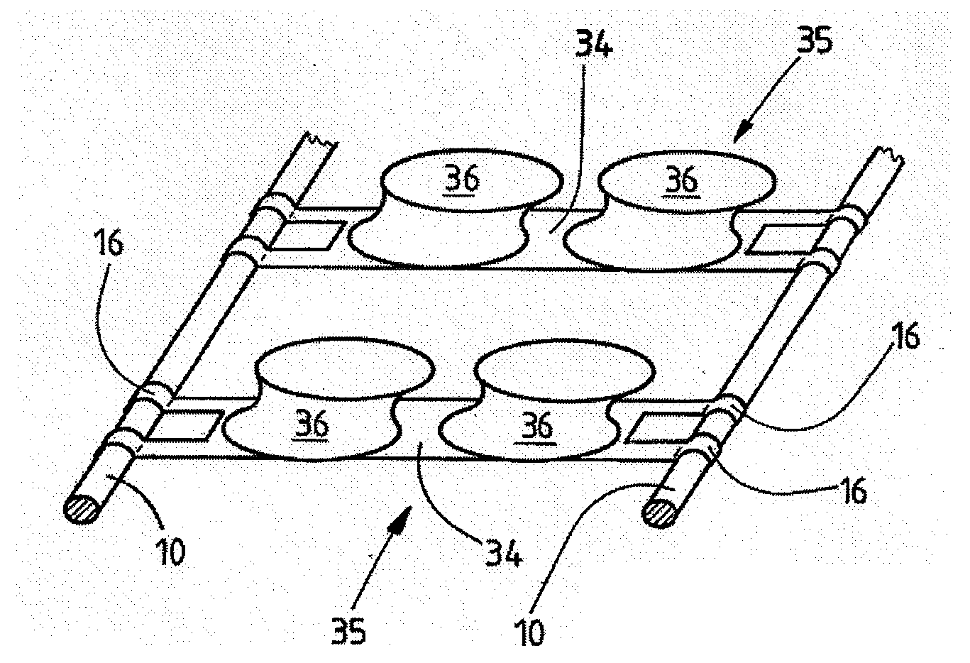
[0034]The supportive spring bases, which are only shown in part in the figures, serve as a support for, for example, a mattress (not shown) of a bed or else of a bunk or a couch.

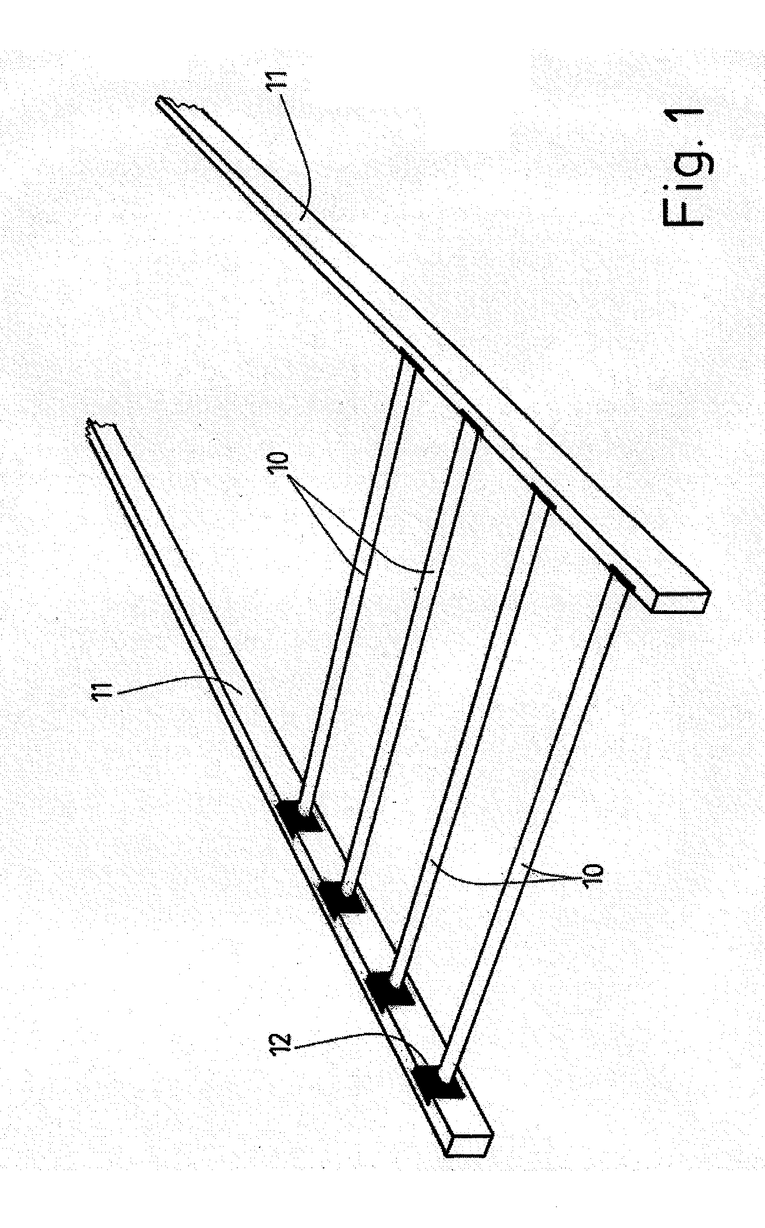
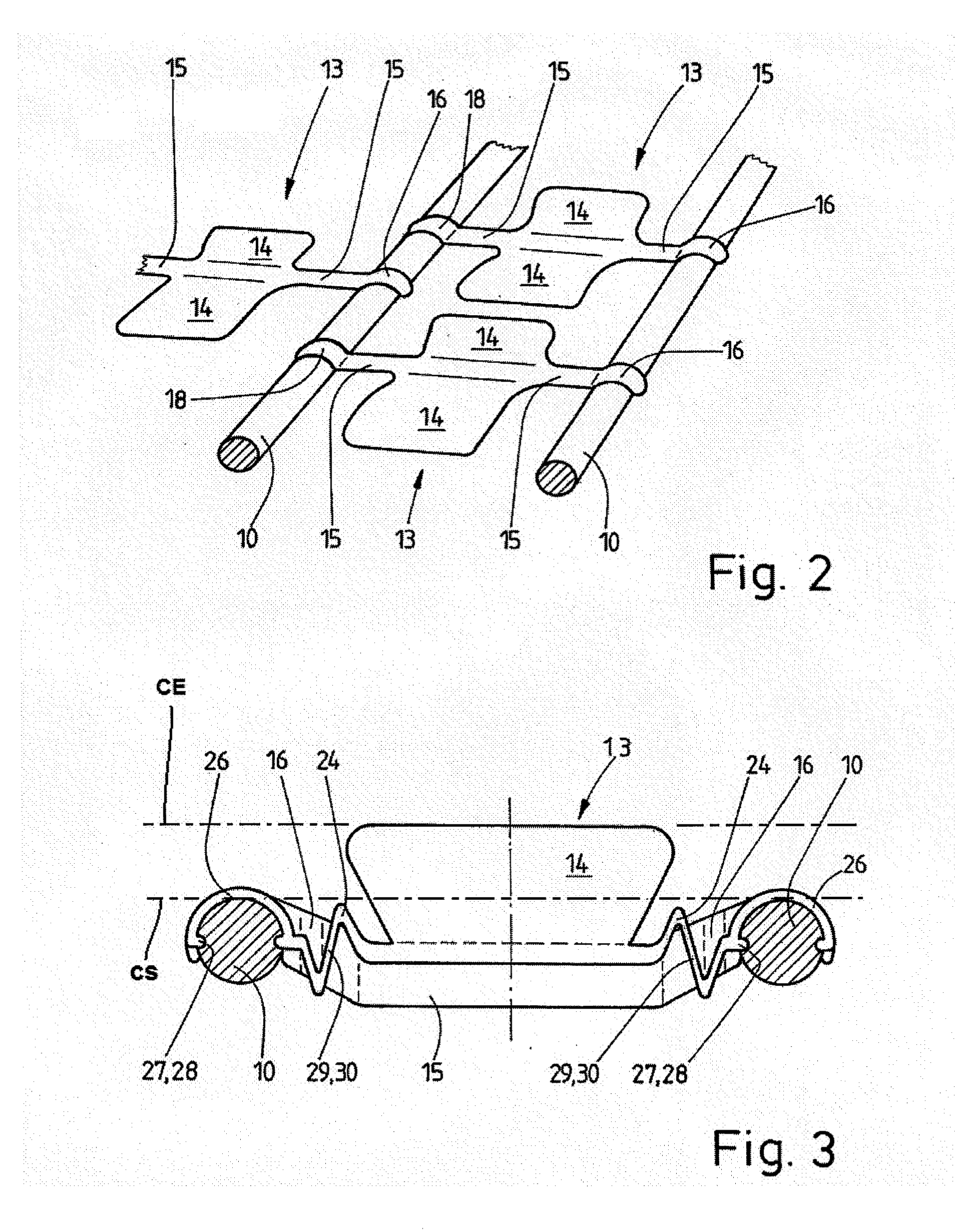
[0035]The supportive spring base has a plurality of preferably identically designed spring slats 10. The individual spring slats 10 run parallel to one another at a distance. The distances between adjacent spring slats 10 may be identical, but also may differ from one another in some regions. All of the spring slats 10 preferably lie in a common, horizontal plane (shown as broken line CS on FIG. 3), but may also be in a different plane or on a slope in some regions, for example in the head region.

[0036]The spring slats 10 are mounted at opposite ends on two parallel longitudinal struts 11. The longitudinal struts 11 extend in the longitudinal direction of the supportive spring base or of the mattress arranged thereon. By contrast, the spring slats 10 run transversely with respect to the longitudinal struts 1...


PUM


Abstract

A supportive spring base for sleeping or reclining having connecting elements (13) for the connection of at least two spring slats (10), the connecting elements (13) having spring elements and / or suspension devices (16) which permit a relative movement of the connecting elements (13) with respect to the spring slats (10).

Description

STATEMENT OF RELATED APPLICATIONS[0001]This patent application is a continuation-in-part of U.S. patent application Ser. No. 10 / 511,709 having a filing date of 20 Jun. 2005, currently pending, which is the United States Patent Cooperation Treaty (PCT) Chapter II National Phase of International Application No. PCT / EP03 / 04523, having an International Application Date of 30 Apr. 2003, designating the United States of America, which in turn claims priority on German Patent Application No. 20207055.7, having a filing date of 3 May 2002, and German Patent Application No. 20209330.1, having a filing date of 15 Jun. 2002.BACKGROUND OF THE INVENTION[0002]1. Technical Field[0003]The invention relates to a supportive spring base for, in particular, a mattress for a place to sleep and / or recline having a plurality of spring slats running at a parallel distance to one another, and having longitudinal struts which run transversely with respect to the spring slats and belong, in particular, to a f...

Claims


Application Information

Patent Timeline
Patent Type & Authority Applications(United States)
IPC IPC(8): A47C23/05A47C23/00A47C23/06
CPCA47C23/002A47C23/068A47C23/06A47C23/05
Inventor JANSEN, KLAUS
Owner THOMAS TECHN INNOVATION
Why Eureka
Try Eureka