Control device and control method for power train

Active Publication Date: 2008-08-07
TOYOTA JIDOSHA KK
View PDF5 Cites 22 Cited by
  • Summary
  • Abstract
  • Description
  • Claims
  • Application Information

AI Technical Summary

Benefits of technology

[0025]Accordingly, during the idle operation of the traveling vehicle wherein the N position is selected, the rotation speed of the second rotating element (transmission member) can be reduced by the up-shift in the transmission mechanism. Therefore, the second rotating element can be speedily locked by the lock control for the second rotating electric machine. As a result, the ISC learning can be implemented in a short period of time.
[0026]As de

Problems solved by technology

Therefore, the engine is idly operated in a state where one of rotating elements (ring gear) constituting the differential mechanism is free with no engagement, and a behavior of an engine rotation speed at the time of the idle speed control (ISC) possibly becomes unstable due to the differential operation in the differential mechanism.
When a learning

Method used


Image

  • Control device and control method for power train
  • Control device and control method for power train
  • Control device and control method for power train

Examples


first modification

[0144

[0145]FIG. 10 is a schematic block diagram for describing a first modification of the ISC and ISC in the power train according to the present embodiment.

[0146]As learnt when FIG. 10 is compared to FIG. 6, according to the first modification, MG2 lock control portion 1300 generates the lock instruction of second MG (MG2) 312 in response to the learning request from learning condition determine portion 1200. Further, an MG1 rotation speed control portion 1400 operated when the learning request is not generated during the idle operation wherein the release position is selected is further provided.

[0147]When the air basic amount Ab is the learning target as described earlier, for example, the ISC learning request is not generated during the idle operation when the engine cooling water is at the predetermined temperature or below. Thus, the ISC learning request may not be generated even in the idle operation wherein the release position is selected, in which case the d-axis lock of ...

second modification

[0157

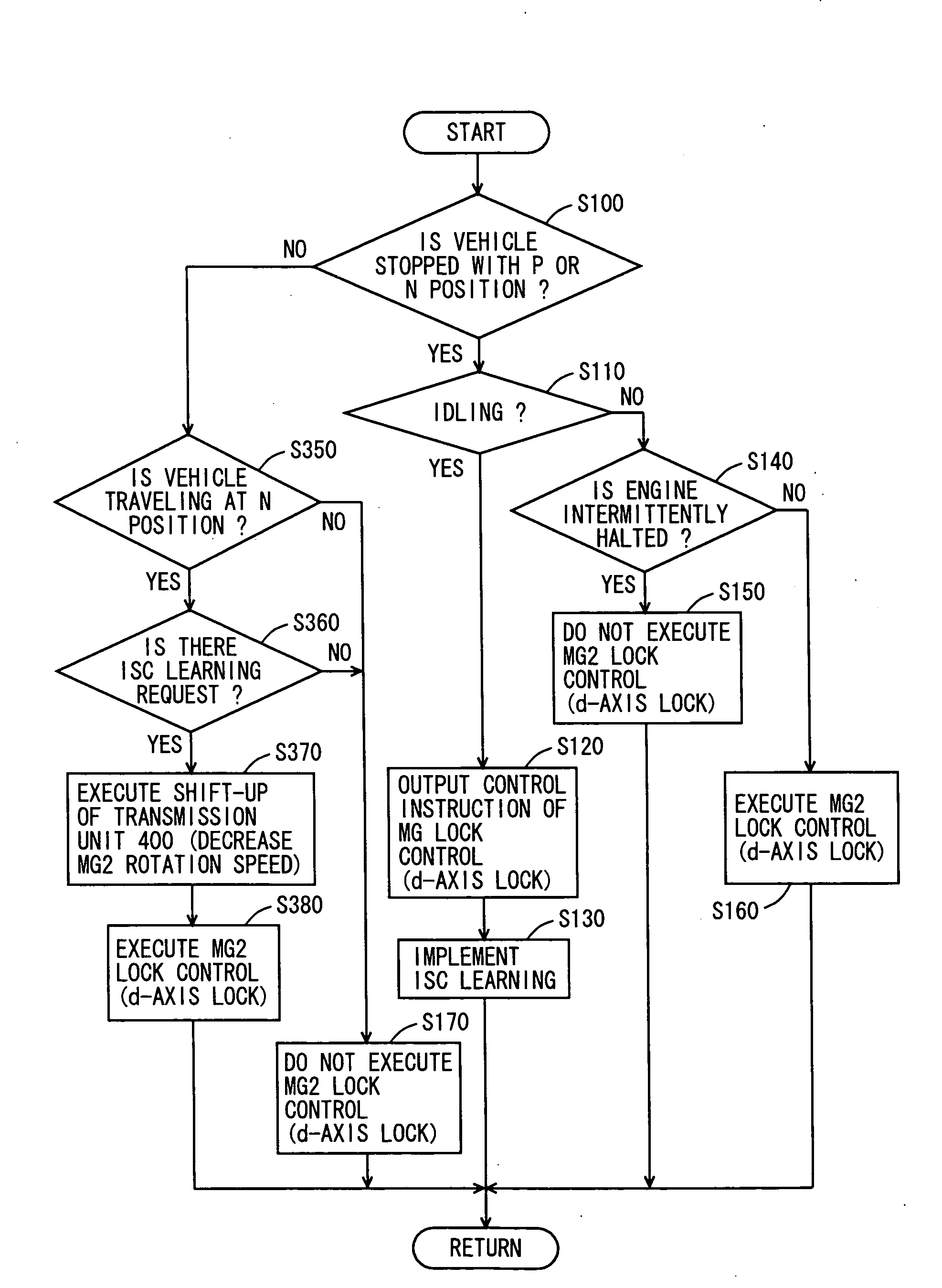
[0158]In a second modification is described a control structure for implementing the ISC learning when the vehicle is traveling and the N position is selected in order to support such a failure to appropriately obtain the opportunity of the ISC learning during the stop of the vehicle.

[0159]As learnt by comparing FIG. 12 to FIG. 6, according to the second modification, an up-shift control portion 1500 is further provided in the control structure shown in FIG. 8. Further, MG2 lock control portion 1300 is operated in a manner similar to the description of FIG. 10, and generates the lock instruction of second MG (MG2) 312 in response to the learning request from learning condition determine portion 1200. Learning condition determine portion 1200 generates the ISC learning request when the other learning conditions are satisfied (temperature of cooling water is higher than predetermined temperature or the like) in the case where the shift position is the N position regardless of if ...


PUM


Abstract

In a power train in which a differential mechanism is coupled with a transmission mechanism, a transmission member is free with no engagement in a second shift portion when a P position or an N position is selected, and a ring gear thereby becomes free in a power split device. During an idle operation with such a shift position, a behavior of an engine rotation speed is retained in a stable manner in the power split device which functions as the differential mechanism through a power supply control (lock control) such that a rotor of a second MG coupled with the ring gear is locked by an electromagnetic force, and then, a learning control of an idle speed control is appropriately implemented.

Description

[0001]This nonprovisional application is based on Japanese Patent Application No. 2007-028038 filed with the Japan Patent Office on Feb. 7, 2007, the entire contents of which are hereby incorporated by reference.BACKGROUND OF THE INVENTION[0002]1. Field of the Invention[0003]The present invention relates to a control device and a control method for a power train, and more particularly to a technology for controlling a power train of a hybrid vehicle including an engine and a rotating electric machine as mechanical power sources.[0004]2. Description of the Background Art[0005]Conventionally, there is known a hybrid vehicle including an internal combustion engine and a rotating electric machine as driving sources. In such a hybrid vehicle, the internal combustion engine and the rotating electric machine are separately used in accordance with a traveling condition of the vehicle. For example, the internal combustion engine is mainly used when the vehicle travels at a high speed, while ...

Claims


Application Information

Patent Timeline
IPC IPC(8): H02P17/00G06F17/00B60K6/445B60K6/543B60K6/547B60L15/20B60L50/16B60W10/06B60W10/08B60W10/10B60W20/00F16H59/08F16H61/00F16H61/68F16H61/684F16H61/688F16H63/50
CPCB60K1/02Y10T477/33B60K6/445B60K6/547B60L11/123B60L11/14B60L15/025B60L2240/421B60L2240/441B60L2240/445B60L2240/485B60L2240/486B60L2260/42B60W10/06B60W10/08B60W10/115B60W20/00B60W2510/0638B60W2510/0676B60W2510/1005B60W2510/1015B60W2510/104B60W2510/107B60W2510/244B60W2520/10B60W2540/10B60W2540/16B60W2710/065B60W2710/081F16H3/54F16H2037/0873H02P21/0025Y02T10/6217Y02T10/6286Y02T10/643Y02T10/7077Y02T10/7258Y02T10/6239Y10T477/347Y10T477/23B60K6/365B60L50/61B60L50/16Y02T10/64Y02T10/62Y02T10/72Y02T10/7072Y02T10/70B60W10/10B60W20/30B60W20/40
Inventor SUGAI, SHINICHIHIGA, MITSUAKI
Owner TOYOTA JIDOSHA KK
Why Eureka
Try Eureka